
Owner manual

www.vishay.com For technical questions, contact: diodes-tech@vishay.com
Document Number: 94337
2 Revision: 19-Mar-08
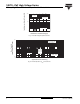
10ETS...PbF High Voltage Series
Vishay High Power Products
Input Rectifier Diode, 10 A
Note
(1)
When mounted on 1" square (650 mm
2
) PCB of FR-4 or G-10 material 4 oz. (140 µm) copper 40 °C/W
For recommended footprint and soldering techniques refer to application note #AN-994
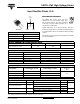
ELECTRICAL SPECIFICATIONS
PARAMETER SYMBOL TEST CONDITIONS VALUES UNITS
Maximum forward voltage drop V
FM
10 A, T
J
= 25 °C 1.1 V
Forward slope resistance r
t
T
J
= 150 °C
20 mΩ
Threshold voltage V
F(TO)
0.82 V
Maximum reverse leakage current I
RM
T
J
= 25 °C
V
R
= Rated V
RRM
0.05
mA
T
J
= 150 °C 0.50
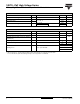
THERMAL - MECHANICAL SPECIFICATIONS
PARAMETER SYMBOL TEST CONDITIONS VALUES UNITS
Maximum junction and storage temperature range T
J
, T
Stg
- 40 to 150 °C
Minimum thermal resistance, junction to case R
thJC
DC operation 2.5
°C/W
Minimum thermal resistance, junction to ambient
(PCB mount)
R
thJA
(1)
62
Soldering temperature T
S
240 °C
Approximate weight
2g
0.07 oz.
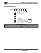
Marking device Case style TO-220AC
10ETS08
10ETS10
10ETS12