
Owner manual

Document Number: 94337 For technical questions, contact: diodes-tech@vishay.com
www.vishay.com
Revision: 19-Mar-08 1
Input Rectifier Diode, 10 A
10ETS...PbF High Voltage Series
Vishay High Power Products
FEATURES/DESCRIPTION
The 10ETS...PbF rectifier series has been
optimized for very low forward voltage drop,
with moderate leakage. The glass passivation
technology used has reliable operation up to
150 °C junction temperature.
Typical applications are in input rectification and these
products are designed to be used with Vishay HPP switches
and output rectifiers which are available in identical package
outlines.
This product has been designed and qualified for industrial
level and lead (Pb)-free.
PRODUCT SUMMARY
V
F
at 10 A < 1 V
I
FSM
200 A
V
RRM
800 to 1200 V
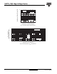
Base
cathode
2
13
Anode
TO-220AC
Cathode
Available
Pb-free
RoHS*
COMPLIANT
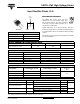
OUTPUT CURRENT IN TYPICAL APPLICATIONS
APPLICATIONS SINGLE-PHASE BRIDGE THREE-PHASE BRIDGE UNITS
Capacitive input filter T
A
= 55 °C, T
J
= 125 °C
common heatsink of 1 °C/W
12.0 16.0 A
MAJOR RATINGS AND CHARACTERISTICS
SYMBOL CHARACTERISTICS VALUES UNITS
I
F(AV)
Sinusoidal waveform 10 A
V
RRM
800 to 1200 V
I
FSM
200 A
V
F
10 A, T
J
= 25 °C 1.1 V
T
J
- 40 to 150 °C
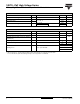
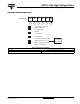
VOLTAGE RATINGS
PART NUMBER
V
RRM
, MAXIMUM
PEAK REVERSE VOLTAGE
V
V
RSM
, MAXIMUM NON-REPETITIVE
PEAK REVERSE VOLTAGE
V
I
RRM
AT 150 °C
mA
10ETS08PbF 800 900
0.510ETS10PbF 1000 1100
10ETS12PbF 1200 1300
ABSOLUTE MAXIMUM RATINGS
PARAMETER SYMBOL TEST CONDITIONS VALUES UNITS
Maximum average forward current I
F(AV)
T
C
= 105 °C, 180° conduction half sine wave 10
A
Maximum peak one cycle
non-repetitive surge current
I
FSM
10 ms sine pulse, rated V
RRM
applied 170
10 ms sine pulse, no voltage reapplied 200
Maximum I
2
t for fusing I
2
t
10 ms sine pulse, rated V
RRM
applied 130
A
2
s
10 ms sine pulse, no voltage reapplied 145
Maximum I
2
√t for fusing I
2
√t t = 0.1 to 10 ms, no voltage reapplied 1450 A
2
√s
* Pb containing terminations are not RoHS compliant, exemptions may apply