
Owner manual

Document Number: 28384 For technical questions, contact: aluminumcaps2@vishay.com
www.vishay.com
Revision: 27-May-09 179
106 PED-ST
Aluminum Capacitors
Power Eurodin Screw Terminals
Vishay BCcomponents
Table 1
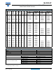
100 000 76 x 105 76 x 146 76 x 220 -
150 000
76 x 146 76 x 220 - -
- 90 x 146 90 x 220 -
220 000
76 x 220 - - -
90 x 146 90 x 220 - -
330 000 90 x 220 - - -
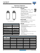
SELECTION CHART FOR C
R
, U
R
AND RELEVANT NOMINAL CASE SIZES (Ø D x L in mm)
C
R
(µF)
U
R
(V)
25 40 63 100
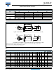
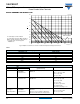
DIMENSIONS in millimeters AND AVAILABLE FORMS
Maximum permissible torque which may be applied to the termination screws: 2 Nm for M5; 2.5 Nm for M6
For accessories refer to datasheet “Mounting Accessories”.
The capacitors are delivered with screws and washers.
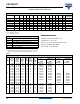
DIMENSIONS in millimeters, MASS AND PACKAGING QUANTITIES
DESIGN DRAWING L ± 1
L
t
± 1
D ± 1 P ± 0.3 T ± 0.2 H ± 0.3 B ± 0.3
d
1
± 0.1
MS - 0Mb
l
b
± 0.1
MASS
(g)
PACKAGING
QUANTITIES
35 x 60 2A 63.3 68.7 35.3 12.8 7.0 4.6 11.0 7.9 M5 9.5 M8 12.0 75 50
35 x 80 2A 81.3 86.7 35.3 12.8 7.0 4.6 11.0 7.9 M5 9.5 M8 12.0 95 50
35 x 105 2A 103.3 108.7 35.3 12.8 7.0 4.6 11.0 7.9 M5 9.5 M8 12.0 130 50
50 x 80 2A 82.8 88.8 51.0 22.2 7.1 4.8 11.0 7.9 M5 9.5 M12 16.0 200 25
50 x 105 2A 104.8 110.8 51.0 22.2 7.1 4.8 11.0 7.9 M5 9.5 M12 16.0 300 25
65 x 105 2A 104.8 110.7 65.0 28.5 7.0 4.6 11.9 7.9 M5 9.5 M12 16.0 480 16
65 x 105 HC 2B 104.8 109.2 65.0 28.5 5.5 3.5 18.0 13.0 M6 8.5 M12 16.0 480 16
76 x 105 2A 105.8 111.7 76.4 31.8 7.0 4.6 11.7 7.9 M5 9.5 M12 16.0 700 12
76 x 105 HC 2B 105.8 110.2 76.4 31.8 5.5 3.5 18.3 13.0 M6 8.5 M12 16.0 700 12
76 x 114 2A 115.8 121.7 76.4 31.8 7.0 4.6 11.7 7.9 M5 9.5 M12 16.0 800 12
A
P
Safety
Vent
Thread M x S
M
b
D
D
L
L
t
H
T
B
d1
l
b
Fig. 2A: Standard M5 disc: screw terminal (ST) and screw terminal bolt nut (STB)
B
P
Safety
Vent
Thread M x S
M
b
D
D
H
T
B
d
1
l
b
L
L
t
Fig. 2B: High current M6 disc: screw terminal (ST) and screw terminal bolt nut (STB)