
User guide

Document Number: 28371 For technical questions, contact: aluminumcaps2@vishay.com
www.vishay.com
Revision: 03-May-10 175
101/102 PHR-ST
Aluminum Capacitors
Power High Ripple Current Screw Terminals
Vishay BCcomponents
Note
(1)
Low ESL designs available on request
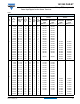
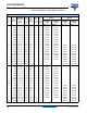
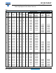
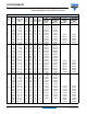
RIPPLE CURRENT AND USEFUL LIFE
Note
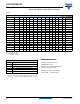
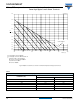
• Calculation example for 102 series. Maximum ripple current multiplier = 1.6 x 1.3 x 1.25 = 2.6
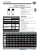
ADDITIONAL ELECTRICAL DATA
PARAMETER CONDITIONS VALUE
Voltage
Surge voltage
≤ 250 V versions U
s
= 1.15 x U
R
≥ 350 V versions U
s
= 1.1 x U
R
Reverse voltage U
rev
≤ 1V
Current
Leakage current in µA
After 1 minute at U
R
I
L1
≤ 0.006 C
R
x U
R
After 5 minutes at U
R
I
L5
≤ 0.002 C
R
x U
R
Inductance
Equivalent series inductance (ESL)
Case Ø D = 35 mm Typ. 13 nH
Case Ø D = 50 mm Typ. 16 nH
Case Ø D = 65 mm Typ. 19 nH
(1)
Case Ø D = 76 mm Typ. 20 nH
(1)
Case Ø D = 90 mm Typ. 21 nH
(1)
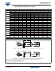
5
4.5
4
3.5
32.5
2
1.5
1
0.5
0
1
1.1
1.2
1.3
1.4
1.5
Air Velocity (m/s)
I
R
Free
I
R
Forced
Fig.3 Multiplier of ripple current (I
R
) as a function of air flow
MAXIMUM RIPPLE CURRENT
PARAMETER CONDITION MAXIMUM RIPPLE CURRENT MULTIPLIER VALUE
Ambient temperature (T
amb
) 70 °C From nomogram; see fig. 4 1.6
Operating frequency (f) 400 Hz From frequency; table 4 1.3
Air flow 2 m/s From air-flow; see fig. 3 1.25