
Owner's manual

095 PLL-4TSI
Vishay BCcomponents
Aluminum Capacitors
Power Long Life 4 Terminal Snap-In
www.vishay.com For technical questions, contact: aluminumcaps2@vishay.com
Document Number: 28393
2 Revision: 08-Aug-08
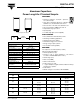
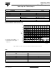
DIMENSIONS in millimeters AND AVAILABLE FORMS
1000
35 x 80
40 x 60
45 x 50
35 x 100
40 x 70
45 x 60
35 x 100
40 x 80
45 x 60
40 x 100
45 x 70
1500
40 x 80
45 x 70
40 x 100
45 x 80
40 x 100
45 x 80
45 x 100
1800 40 x 100 45 x 100 45 x 100 -
2200 45 x 100 - - -
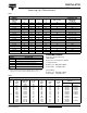
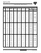
SELECTION CHART FOR C
R
, U
R
AND RELEVANT NOMINAL CASE SIZES (Ø D x L in mm)
C
R
(µF)
U
R
(V)
350 400 420 450
1.3
(5x)
2.5
1
2
3
4
-
10 ± 0.1
20 ± 0.1
17.5 ± 0.1
20 ± 0.1
MGB267-1
1.3
(4x)
2.5
1
2
3
-
17.5 ± 0.1
7.5 ± 0.1
15 ± 0.1
L
1
4
-
3
2
4.9 ± 0.2
Ø D + 1 max.
L + 5 max.
Fig.3 Mounting hole diagram viewed
from component side
Case Ø D = 35 mm
Case Ø D = 35 mm
Fig.2 Printed wiring
pin version
Case Ø D = 40 mm
Fig.5 Mounting hole diagram viewed
from component side
Case Ø D = 40 mm
Fig.4 Printed wiring
pin version
22.5
Ø D
60°
60°
Bottom view
L
max.
6.3 ± 1
d
ummy dummy
C
B
A
60
°
60
°
2 ± 0.1
(4x)
22.5
± 0.1
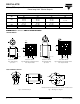
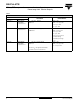
Dummy terminals (A and C) must be free from the electrical circui
t
Fig. 6 4-Terminal Snap-in
Fig. 7 Mounting hole diagram
FOUR TERMINAL SNAP-IN
PRINTED WIRING
Ø D + 1 max.
L + 5 max.
CCA976-1
L
12
3
-
4.9 ± 0.2