6121 Baker Road, Suite 108 Minnetonka, MN 55345 Phone (952) 933-6190 Fax (952) 933-6223 1-800-274-4284 www.chtechnology.com Thank you for downloading this document from C&H Technology, Inc. Please contact the C&H Technology team for the following questions - Technical Application Assembly Availability Pricing Phone – 1-800-274-4284 E-Mail – sales@chtechnology.com www.chtechnology.com - SPECIALISTS IN POWER ELECTRONIC COMPONENTS AND ASSEMBLIES - www.chtechnology.
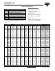
058/059 PLL-SI Vishay BCcomponents Aluminum Capacitors Power Long Life Snap-In FEATURES • Polarized aluminum non-solid electrolyte electrolytic capacitors, • Large types, minimized dimensions, cylindrical aluminum case, insulated with a blue sleeve RoHS COMPLIANT • Very long useful life: up to 10 000 hours at 105 °C • Extended temperature range: 105 °C Fig.
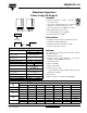
058/059 PLL-SI Aluminum Capacitors Power Long Life Snap-In Vishay BCcomponents SELECTION CHART FOR CR, UR AND RELEVANT NOMINAL CASE SIZES FOR 058 SERIES (Ø D x L in mm) CR (µF) 2200 3300 4700 6800 10 000 15 000 22 000 33 000 47 000 UR (V) 10 16 - - 25 40 50 63 100 22 x 25 22 x 30 25 x 30 30 x 30 35 x 40 - - - - 22 x 40 25 x 40 30 x 50 - 22 x 25 22 x 30 25 x 30 30 x 30 30 x 40 35 x 50 - - - 22 x 40 25 x 40 25 x 50 - 22 x 25 22 x 30 25 x 30 30 x 30 30 x 40 35 x
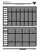
058/059 PLL-SI Aluminum Capacitors Power Long Life Snap-In Vishay BCcomponents DIMENSIONS in millimeters AND AVAILABLE FORMS TWO TERMINAL SNAP-IN ØD + TERMINAL L + 2 max. L 10 ± 0.1 - TERMINAL Bottom view +0 5.8 -1 mm The minus terminal can be marked with a black dot or with an imprinted ‘−’ sign. Ø 2 ± 0.1 (2 x) Fig.3 Mounting hole diagram Fig.2 Two terminal snap-in THREE TERMINAL SNAP-IN ØD Ø 2 ± 0.1 (2 x) Ø 2.5 ± 0.1 + TERMINAL L + 2 max. L 10 ± 0.1 - TERMINAL 3.3 ± 0.
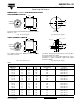
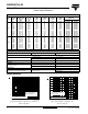
058/059 PLL-SI Aluminum Capacitors Power Long Life Snap-In Vishay BCcomponents ORDERING EXAMPLE ELECTRICAL DATA SYMBOL Electrolytic capacitor 058 series 10 000 µF/25 V; ± 20 % Nominal case size: Ø 30 x 40 mm DESCRIPTION CR rated capacitance at 100 Hz IR rated RMS ripple current at 100 Hz or ≥ 10 kHz and 105 °C IL1 max. leakage current after 1 minute at UR IL5 max. leakage current after 5 minutes at UR ESR max. equivalent series resistance at 100 Hz Z max.
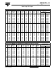
058/059 PLL-SI Aluminum Capacitors Power Long Life Snap-In Vishay BCcomponents ELECTRICAL DATA AND ORDERING INFORMATION FOR 058 SERIES (Ø D x L in mm) UR (V) 50 63 100 CR 100 Hz (µF) 1000 1500 2200 2200 3300 3300 4700 4700 6800 6800 10 000 680 1000 1500 1500 2200 2200 3300 3300 4700 4700 6800 330 470 680 680 1000 1000 1500 1500 2200 2200 3300 NOMINAL CASE SIZE ØDxL (mm) 22 x 25 22 x 30 25 x 30 22 x 40 30 x 30 25 x 40 30 x 40 25 x 50 35 x 40 30 x 50 35 x 50 22 x 25 22 x 30 25 x 30 22 x 40 30 x 30 25 x
058/059 PLL-SI Aluminum Capacitors Power Long Life Snap-In Vishay BCcomponents ELECTRICAL DATA AND ORDERING INFORMATION FOR 059 SERIES 33 47 68 68 100 100 150 150 220 220 330 47 68 68 100 100 150 150 220 220 330 385 400 IR 100 Hz 105 °C (A) 0.32 0.41 0.53 0.52 0.72 0.72 0.99 0.99 1.31 1.31 1.75 0.30 0.38 0.41 0.55 0.55 0.68 0.78 0.94 0.94 1.
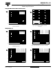
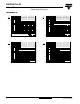
058/059 PLL-SI Aluminum Capacitors Power Long Life Snap-In Vishay BCcomponents EQUIVALENT SERIES RESISTANCE (ESR) 10 1.5 3 ESR ESR0 10 ESR ESR0 Curve 1: UR ≥ 250 V Curve 2: UR = 200 V Curve 3: UR ≤ 200 V 1 2 2 1.0 2 3 10 1 1 0.5 1 2, 3 1 ESR0 = typical at 20 °C and 100 Hz 10-1 - 100 - 50 0 Curve 1: UR = 10 to 100 V Curve 2: UR = 200 to 400 V ESR0 = typical at 20 °C and 100 Hz 50 100 0 101 150 10 2 10 3 f (Hz) 10 4 Tamb (°C) Fig.
058/059 PLL-SI Aluminum Capacitors Power Long Life Snap-In Vishay BCcomponents IMPEDANCE (Z) 10 5 10 Curve 1: 100 µF Curve 2: 220 µF Curve 3: 330 µF Curve 4: 1000 µF Curve 5: 2200 µF Z (mΩ) 10 1 4 Curve 6: 3300 µF Curve 7: 4700 µF Curve 8: 6800 µF Curve 9: 10 000 µF Curve 10: 15 000 µF 5 Curve 1: 150 µF Curve 2: 330 µF Curve 3: 470 µF Curve 4: 1500 µF Curve 5: 3300 µF Z (mΩ) 10 4 2 3 1 Curve 6: 4700 µF Curve 7: 6800 µF Curve 8: 10 000 µF Curve 9: 15 000 µF Curve 10: 22 000 µF 2 3 Case Ø D x
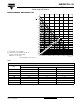
058/059 PLL-SI Aluminum Capacitors Power Long Life Snap-In Vishay BCcomponents RIPPLE CURRENT AND USEFUL LIFE 2.7 IA IR 2.6 2.5 2.4 2.3 2.2 2.1 2.0 1.9 1 2 1. 5 life multiplier 1. 1.8 2 5 2. 3 1.7 4 5 1.6 7 30 Useful life at 105 °C and IR applied: 5000 hours for ≤ 50 V types 20 (1) 15 IA = actual ripple current at 100 Hz IR = rated ripple current at 100 Hz and 105 °C 40 60 0 10 0 15 0 20 0 30 0 40 0 60 1.4 1.3 10 1.5 1.2 1.1 1.0 0.8 0.5 0.
058/059 PLL-SI Vishay BCcomponents Aluminum Capacitors Power Long Life Snap-In Table 5 TEST PROCEDURES AND REQUIREMENTS TEST NAME OF TEST Endurance REFERENCE IEC 60384-4/ EN130300 subclause 4.13 PROCEDURE (quick reference) Tamb = 105 °C; UR applied; ≤ 50 V types: 2000 hours; ≥ 63 V types: 5000 hours REQUIREMENTS UR ≤ 100 V; ΔC/C: ± 15 % UR > 100 V; ΔC/C: ± 10 % ESR ≤ 1.3 x spec. limit Z ≤ 2 x spec. limit IL5 ≤ spec. limit Useful life CECC 30301 subclause 1.8.
Legal Disclaimer Notice Vishay Disclaimer All product specifications and data are subject to change without notice. Vishay Intertechnology, Inc., its affiliates, agents, and employees, and all persons acting on its or their behalf (collectively, “Vishay”), disclaim any and all liability for any errors, inaccuracies or incompleteness contained herein or in any other disclosure relating to any product.