
User guide

050/052 PED-PW
Vishay BCcomponents
Aluminum Capacitors
Power Eurodin Printed Wiring
www.vishay.com For technical questions, contact: aluminumcaps2@vishay.com
Document Number: 28345
128 Revision: 10-Mar-09
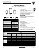
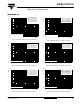
MOUNTING
When a number of capacitors are connected in a bank, they must not be closer together than 15 mm, when no derating of ripple
current and/or temperature is applied.
Pin numbers 2, 3 and 4 (if present) must be free from the electrical circuit.
Table 1
Note
(1)
Not available in SL versions
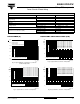
Case Ø D = 35 mm
Fig.6 Printed wiring pin version
4.9 ± 0.2
-
3
L + 5 max.
Ø D + 1 max.
Case Ø D = 35 mm
Fig.7 Mounting hole diagram viewed from component side
15 0.1
1.3
(4 x)
7.5 ± 0.1
17.5 0.1
2.5
1
2
3
-
±
±
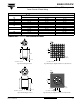
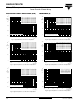
Case Ø D = 40 mm
Fig.8 Printed wiring pin version
L
1
4
-
3
2
L + 5 max.
4.9 ± 0.2
Ø D + 1 max.
1.3
(5 x)
17.5 ± 0.1
2.5
20 ± 0.1
1
2
3
4
-
10 ± 0.1
20 ± 0.1
Fig.9 Mounting hole diagram viewed
from component outside
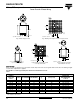
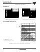
Case Ø D = 40 mm
Case Ø D = 40 mm
Fig.10 Solder-lug version (SL):
only available in 050 series
9 ± 1
0.8
Ø D + 1 max.
L + 2 max.
10
± 05
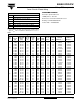
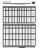
DIMENSIONS in millimeters, MASS AND PACKAGING QUANTITIES
NOMINAL
CASE SIZE
Ø D x L
Ø D
max.
L
max.
SL VERSIONS
L
max.
PW VERSIONS
MASS
(g)
PACKAGING QUANTITIES
(units per box)
CARDBOARD
BOX DIMENSIONS
L x W x H
25 x 30 26 32 35 ≈ 24 100 290 x 280 x 50
25 x 40 26 42 45 ≈ 28 100 290 x 280 x 60
30 x 40 31 42 45 ≈ 38 100 340 x 330 x 60
35 x 40 36 42 45 ≈ 51 50 390 x 198 x 60
35 x 50 36 52 55 ≈ 66 50 390 x 198 x 70
40 x 40
(1)
41 - 45 ≈ 78 50 440 x 223 x 60
40 x 50 41 52 55 ≈ 82 50 440 x 223 x 70
40 x 70 41 72 75 ≈ 110 25 230 x 230 x 90
40 x 100 41 102 105 ≈ 176 25 230 x 230 x 120