6121 Baker Road, Suite 108 Minnetonka, MN 55345 Phone (952) 933-6190 Fax (952) 933-6223 1-800-274-4284 www.chtechnology.com Thank you for downloading this document from C&H Technology, Inc. Please contact the C&H Technology team for the following questions - Technical Application Assembly Availability Pricing Phone – 1-800-274-4284 E-Mail – sales@chtechnology.com www.chtechnology.com - SPECIALISTS IN POWER ELECTRONIC COMPONENTS AND ASSEMBLIES - www.chtechnology.
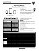
050/052 PED-PW Vishay BCcomponents Aluminum Capacitors Power Eurodin Printed Wiring FEATURES PW PW • Polarized aluminum electrolytic capacitors, non-solid electrolyte • Large types, cylindrical aluminum case, RoHS insulated with a blue sleeve COMPLIANT • Provided with keyed polarity • 050 series also available in solder-lug (SL) versions • Very long useful life: 15 000 hours at 85 °C • Low ESR, high ripple current capability • High resistance to shock and vibration SL Fig.
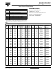
050/052 PED-PW Aluminum Capacitors Power Eurodin Printed Wiring Vishay BCcomponents SELECTION CHART FOR CR, UR AND RELEVANT NOMINAL CASE SIZES FOR 052 SERIES (Ø D x L) UR (V) CR (µF) 250 47 68 100 150 385 25 x 30 25 x 40 30 x 40 35 x 40 35 x 50 40 x 40 40 x 50 40 x 70 - 25 x 30 25 x 40 30 x 40 35 x 40 35 x 50 40 x 40 40 x 50 40 x 70 220 330 470 680 1000 400 25 x 30 25 x 40 30 x 40 35 x 40 35 x 50 40 x 40 40 x 50 40 x 70 40 x 100 - DIMENSIONS in millimeters AND AVAILABLE FORMS 2.5 Ø D + 1 max.
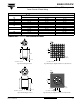
050/052 PED-PW Aluminum Capacitors Power Eurodin Printed Wiring Vishay BCcomponents 3 - 2.5 Ø D + 1 max. 2 3 15 ± 0.1 1 L + 5 max. 1.3 (4 x) 7.5 ± 0.1 4.9 ± 0.2 17.5 ± 0.1 Case Ø D = 35 mm Case Ø D = 35 mm Fig.7 Mounting hole diagram viewed from component side Fig.6 Printed wiring pin version 0.8 2.5 1 Ø D + 1 max. - - 3 2 4 3 2 1 L + 2 max. 1.3 (5 x) L + 5 max. L 4 20 ± 0.1 Ø D + 1 max. 9±1 10 ± 0.1 17.5 ± 0.1 Case Ø D = 40 mm 4.9 ± 0.
050/052 PED-PW Aluminum Capacitors Power Eurodin Printed Wiring ORDERING EXAMPLE ELECTRICAL DATA SYMBOL Vishay BCcomponents Electrolytic capacitor 050 series DESCRIPTION CR rated capacitance at 100 Hz 10 000 µF/25 V; - 10/+ 30 % IR rated RMS ripple current at 100 Hz, 85 °C or at 20 kHz, 70 °C Nominal case size: Ø 35 x 50 mm; PW version IL1 max. leakage current after 1 minute at UR IL5 max. leakage current after 5 minutes at UR ESR max. equivalent series resistance at 100 Hz Z max.
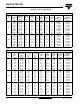
050/052 PED-PW Aluminum Capacitors Power Eurodin Printed Wiring Vishay BCcomponents ELECTRICAL DATA AND ORDERING INFORMATION FOR 050 SERIES UR (V) 63 100 CR 100 Hz (µF) NOMINAL CASE SIZE ØDxL (mm) 1000 1500 2200 3300 4700 4700 6800 10 000 15 000 470 680 1000 1500 2200 2200 3300 4700 6800 25 x 30 25 x 40 30 x 40 35 x 40 35 x 50 40 x 40 40 x 50 40 x 70 40 x 100 25 x 30 25 x 40 30 x 40 35 x 40 35 x 50 40 x 40 40 x 50 40 x 70 40 x 100 IR 100 Hz 85 °C (A) 1.8 2.5 3.1 3.6 4.4 3.8 4.7 6.2 8.5 1.4 1.9 2.
050/052 PED-PW Aluminum Capacitors Power Eurodin Printed Wiring Vishay BCcomponents ADDITIONAL ELECTRICAL DATA PARAMETER CONDITIONS VALUE Voltage Surge voltage ≤ 250 V versions ≥ 385 V versions Us = 1.15 x UR Us = 1.1 x UR Urev ≤ 1 V After 1 minute at UR After 5 minutes at UR IL1 ≤ 0.006 CR x UR + 4 µA IL5 ≤ 0.002 CR x UR + 4 µA Case Ø D = 25 mm Case Ø D = 30 and 35 mm Case Ø D = 40 mm max. 25 nH max. 30 nH max.
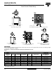
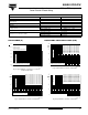
050/052 PED-PW Aluminum Capacitors Power Eurodin Printed Wiring Vishay BCcomponents EQUIVALENT SERIES RESISTANCE (ESR) 105 Curve 1: case Ø D x L = 25 x 30 mm Curve 2: case Ø D x L = 25 x 40 mm Curve 3: case Ø D x L = 39 x 40 mm Curve 4: case Ø D x L = 35 x 40 mm Curve 5: case Ø D x L = 40 x 40 mm Curve 6: case Ø D x L = 35 x 50 mm Curve 7: case Ø D x L = 40 x 50 mm Curve 8: case Ø D x L = 40 x 70 mm ESR (mΩ) 104 103 10 1 2 3 4 5 6 7 8 2 ESR at 100 Hz and UR = 385 V 0 103 Z (mΩ) 50 102 10 Z = at
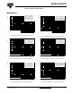
050/052 PED-PW Aluminum Capacitors Power Eurodin Printed Wiring Vishay BCcomponents IMPEDANCE (Z) 102 1 Z (Ω) 2 10 102 Curve 1: 68 µF, 385 V Curve 2: 150 µF, 250 V Curve 3: 680 µF, 100 V Curve 4: 1500 µF, 63 V Curve 5: 6800 µF, 10 V Z (Ω) 1 10 2 Curve 1: 47 µF, 385 V Curve 2: 220 µF, 250 V Curve 3: 1000 µF, 100 V Curve 4: 2200 µF, 63 V Curve 5: 10 000 µF, 10 V 3 3 4 1 4 1 5 5 -1 10 10 10-2 -1 Case Ø D x L = 25 x 40 mm 10-2 2 10 10 3 10 10 4 5 10 6 Case Ø D x L = 35 x 40 mm 7
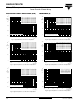
050/052 PED-PW Aluminum Capacitors Power Eurodin Printed Wiring Vishay BCcomponents IMPEDANCE (Z) 102 102 Case Ø D x L = 40 x 70 mm Z (Ω) Curve 1: 470 µF, 385 V Curve 2: 1000 µF, 250 V Curve 3: 4700 µF, 100 V Curve 4: 10 000 µF, 63 V Curve 5: 47 000 µF, 10 V 10 1 Curve 1: 6800 µF, 100 V Curve 2: 15 000 µF, 63 V Curve 3: 68 000 µF Z (Ω) 10 1 2 2 1 1 3 3 4 10 -1 10 5 -1 Case Ø D x L = 40 x 100 mm 10-2 10-2 10 102 103 104 105 106 f (Hz) 107 102 10 103 104 105 106 f (Hz) 107 Fig.
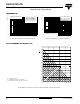
050/052 PED-PW Aluminum Capacitors Power Eurodin Printed Wiring Vishay BCcomponents Table 4 MULTIPLIER OF RIPPLE CURRENT (IR) AS A FUNCTION OF FREQUENCY IR MULTIPLIER FREQUENCY (Hz) 50 0.83 100 1.00 200 1.10 400 1.15 1000 1.19 ≥ 2000 1.20 Table 5 TEST PROCEDURES AND REQUIREMENT TEST NAME OF TEST Endurance PROCEDURE (quick reference) REFERENCE REQUIREMENTS IEC 60384-4/ Tamb = 85 °C; UR applied; UR ≤ 100 V; ΔC/C: ± 15 % EN130300 5000 hours UR > 100 V; ΔC/C: ± 10 % subclause 4.
Legal Disclaimer Notice Vishay Disclaimer All product specifications and data are subject to change without notice. Vishay Intertechnology, Inc., its affiliates, agents, and employees, and all persons acting on its or their behalf (collectively, “Vishay”), disclaim any and all liability for any errors, inaccuracies or incompleteness contained herein or in any other disclosure relating to any product.