MULTI-SPORT TRAILER Model 48810 Assembly Instructions C.E. Smith Co. Greensboro NC USA cesmith.com 800-334-2490 48810-INST.
MULTI-SPORT TRAILER Model 48810 ASSEMBLY INSTRUCTIONS Thanks for purchasing a SMITH Multi-Sport Trailer, the best value in a small craft trailer on the market today. Take a few minutes now and read thru these instructions to familiarize yourself with the step by step assembly process before you begin. Your trailer has come to you in (3) cartons. Take the time now to open all 3 cartons, sort through and divide the contents into 7 groups as shown in the following photos.
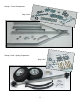
Group 1: Frame Components Bag 11463 Group 2: Axle / Spring Components Bag 11467 2
Group 3: Fender Components Bag 11464 Group 4: Lighting components Bag 11468 Group 5: Coupler Components Bag 11494 3
Group 6: Winch Stand Components Bag 11490 Group 7: Bunk boards and bunk mounting hardware.
FRAME ASSEMBLY (Group 1) We will start by assembling the basic frame using components from group 1. We are going to build the frame upside down, wheels up, so we will be turning all parts “bottom side up” as we assemble the frame, then we will flip it over later to complete the assembly. 1. Layout the frame rails with 8 spring bracket holes facing up as shown. 2. Attach the spring brackets to the frame rail holes.
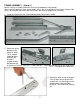
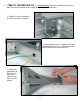
4. Snap the wire protection grommet into the 9/16” hole of the side of the tongue near the skid holes as shown. 5. Pass the wires through the grommet and out as shown. Roll up as much wire outside the grommet as the white wire is long as shown. 6. We will let gravity do the work of threading the wires. Pass the wires down through a large socket and back up again as shown. No need for a knot. With the tongue tipped up, feed the heavy socket into the end of the tongue.
7. Position the tongue in between the rails as shown (skid stand holes still facing up). Pass the wires through the tongue support and install the 4-1/2” bolt up through the support and tongue from the bottom being careful not to pinch the wires. Add washer and nut hand tight only. 8. Bolt the tongue support to the rails using 3/8” x 1” carriage head bolts. Heads go on the outside thru the square holes. Washers and nuts on the inside as shown. Assemble HAND TIGHT ONLY for now.
. Attach the frame rails to the tongue using two ½” x 3-1/4” bolts. Use a washer on both sides, under the bolt heads and under both nuts. Assemble HAND TIGHT ONLY. 10. Lay the 2 frame cross members in between the frame rails as shown. Position them with the two holes in the middle facing DOWN as shown in the inset. Bolt the frame rails to the cross members using 3/8” x 1” carriage bolts and nuts. The carriage heads go to the outside. No washers are needed here. Assemble HAND TIGHT ONLY.
11. TIME TO TIGHTEN BOLTS: It’s very important to follow this tightening sequence in order to insure the tongue will be straight with the frame after tightening. 1) Tighten the 8 nuts holding the ends of the two cross members. 2) Evenly tighten the 4 nuts holding the tongue support to the frame rails. Double check that you installed washers under the nuts. 3) Tighten the tongue bolts to the frame rails. Don’t over tighten or you may crush the tongue.
4) Tighten the big bolt thru tongue and tongue support. Not too tight, don’t crush the tongue. Your main frame assembly is now complete and should look like this.
ASSEMBLING THE SPRINGS AND AXLE (GROUP 2) 1. Set the envelope containing the Manufacturer’s Certificate of Origin (MCO) and VIN Labels aside in a safe place. 2. Spin the axle until the spring centering holes are facing up as shown. 3. We will attach one spring at a time to the axle. Lay a spring, 2 U-bolts, 4 nuts and 1 tie plate out as shown. Note the center bolt on the spring fits into the spring centering hole in the axle.
4. Fit the U-bolts under the axle and up thru the tie plate as shown. Note the spring centering bolt fits into the center hole of the tie plate. 5. Tighten each nut a couple turns each evenly drawing the axle up to the spring. As the assembly closes, guide the spring centering bolt into the spring centering hole in the axle. DO NOT FULLY TIGHTEN THE NUTS at this time. They will be tightened after the axle spring assembly has been mounted to the frame. 6. Repeat assembly process for the second spring.
8. Insert the spring eyes into the front hanger brackets and bolt in place with 1/2” x 3” bolts and self locking nuts. *** IMPORTANT **** As you tighten the shackle bolts DO NOT CRUSH the bracket at all. This is a hinge and it needs room to move. Tighten only until the bolt head and nut pull in and touch the sides of the hanger bracket 9. Now that the axle / spring assembly is attached to the frame, we can return to the U-bolts and evenly tighten the 8 U-bolt nuts.
11. Carefully, flip the trailer over onto its tires. 12. Tighten the lug nuts to 75-85 ft lb.
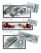
ASSEMBLING FENDERS (Group 3) 1. Connect all 4 fender brackets to the fenders using 3/8" x 3/4” slot head screws and nuts. Assemble loosely with nuts to the inside of the fenders as shown. No washers here. Fully tighten all 8 screws and nuts.
2. Note that either fender will fit on either side of the trailer. 3. As we ready to mount the fenders onto the frame, note that you will install a washer under the head of each bolt and under each nut. 4. Using the 3/8” x 1” bolts, washers and nuts, attach the fender brackets to the slotted holes in the frame as shown. Hand tight only all 4 mounting bolts. 5. Tighten both bolts fully and repeat for other side.
LIGHTS AND WIRING (Group 4) Trailer Wiring Color Code • Brown = Running Lights • Yellow = Left Signal / Left Brake • Green = Right Signal / Right Brake • White = Ground 1. Attach the tail lamp brackets to the frame as shown. Use 3/8” x 1” carriage head bolt and nut. No washer is needed. 2. Sandwich the license plate mounting bracket in between the left side lamp and the left side tail lamp bracket. Attach the tail light using the nuts provided in the lamp kit as shown. Then mount the right side lamp.
3. Attach both running lights to frame at the three holes just forward of the fenders. The mounting stud goes thru the middle hole. the wire goes thru one of the other 2 holes. Tighten using the nut provided with the kit. 4. Stretch the wire out of the grommet to check that the same length of wire is outside the grommet as the white wire is long. Then coil the wire so it is sure not to be pulled back into the grommet. 5. Route the GREEN / BROWN wire along the RIGHT side of the frame.
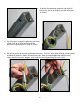
7. Route the wires thru the cross member as shown. Carefully tuck the wires into the frame rails so you are sure of their permanent place along the frame. About 2” behind the side marker lamp use your knife tip to carefully divide about 1/2” of the 2 conductors taking great care to only divide the wires without cutting either conductor. Then grasp and separate by hand about 3” of wire as shown above 8. Press brown wire into the Quick Tap connector as shown.
9. Route the wires to the tail lights and thru the slot under the lamp bracket. Allow extra wire as shown below so your installation can end up like the photo below. Extra length makes working with the connections much easier. 10. Strip ½” off the end of the wire exposing the copper strands and twist the exposed strands to stiffen them. 11. There are holes in the back of each tail lamp marked by color.
COUPLER ASSEMBLY (Group 5) 1. Strip 3/8” of the white wire insulation and crimp on the ring connector as shown. 2. The tongue skid and safety chains are attached to the tongue by one 3/8” x 11/2” hex bolt. Assemble as shown with washers above and below the chain ends.
3. Take the skid and chain assembly to the tongue and insert the bolt up through the skid bolt hole on the bottom of the tongue as shown. 4. Place the white wire ring terminal over the bolt, and install the nut hand tight. 5. Make sure the rear of the skid is in its receiving hole in the tongue, and tighten the BOLT, while holding the NUT stationary. Don’t turn the nut. 6. Install the coupler onto the tongue and fully tighten as shown.
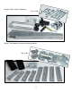
WINCH STAND ASSEMBLY (Group 6) The best winch stand setup for each style and size craft is a little different. In this step we will assemble the stand generically, then later, after you have mounted and fitted your bunks to fit your craft, return and make adjustments to the winch stand to best suit your application or craft. No matter what you are trailering, remember, the winch stand assembly has 3 purposes. 1) To provide a fixed point for the winch to pull the craft up onto the trailer.
2. The winch may be mounted inside the bow stop bracket as shown here, or it may be mounted independently above or below the winch, whichever works better for your craft. Mount hand tight for now where you think may be best. Use 3/8” x 1” bolts washers and nuts to attach. The washers are used over the slotted holes. They are not needed when the hole used is round. 3. Attach the bow stop of your choice. Just tighten till all the slack is out of the bolt, don’t over tighten.
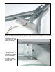
BUNK ASSEMBLY (Group 7) In this step we will go over generic bunk mounting. For your craft the width, spacing, height and angle of the bunks will be unique to best support your hull for trailering over the road. Included with your trailer are 4 short and 4 long brackets shown above. Use 4, the other 4 will be left over. Choose the length brackets that best hold your craft as low as possible over the frame without risk of bumping it or the fenders.
3. Attach the brackets to the frame cross members at the approximate best positions. Attach using U-bolts, washers and nuts. The dimple side of the brackets engages the open edge of the frame C channel. Attach all 4 brackets leaving loose enough to slide on the frame. 4. Lay a carpeted bunk board on the swivel brackets with the stapled side down to the brackets and choose how much overhang you like off the front and back ends. 5.
8. With both bunks in place, tighten the swivel brackets at the desired angle, width and height to best fit your craft. 9. Set your craft on the trailer and make any fit improvements as needed. 10. Lift your tongue. You should have a tongue weight of about 10% of the weight of the combined load. Slide the craft forward or back on the trailer until the tongue weight feels good, then move the winch stand assembly to meet the bow of the craft at this position and tighten everything down. 11.
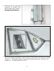
SAMPLE SETUPS FOR A VARIETY OF CRAFT: Jon Boats and Inflatables Bunks Mounted Flat and Low 28
Twin Troller Bunks Mounted High and Narrow up in the Tunnel 29
Canoes And Dingies Bunks Mounted Angled To Match Hull 30
Kayaks Bunks Mounted Perpendicular to Frame 31