
Troubleshooting Guides User guide

Page 1
TG82A
Table of Contents
Section A: Component Description ..................... 2 – 3
Section B: On-vehicle Troubleshooting ............... 4 – 5
Indicates special instructions on
installation, operation or mainte-
nance that are important but not
related to personal injury hazards.
NOTICE
Troubleshooting Guide
for N1617 Alternator
Testing Guidelines
Professional service technicians rely on the following
guidelines when testing electrical components.
Voltage testing:
• Set meter to proper scale and type (AC or DC).
• Be sure to zero the meter scale or identify the meter
burden by touching meter leads together. Meter bur-
den must be subtracted from final reading obtained.
• Be sure the meter leads touch source area only.
Prevent short circuit damage to test leads or source
by not allowing meter leads to touch other pins or
exposed wires in test area.
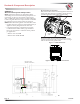
Voltage drop testing:
• Measure voltage between B+ on alternator or source
and B- (ground) on alternator or source. Record
obtained reading. Move to batteries or other source
and measure again between B+ and B- terminals on
battery or other source. Difference between the two
readings represents voltage lost within the circuit
due to but not limited to inadequate cable gage or
faulty connections.
• Voltage drop measurements must be taken with
all electrical loads or source operating.
Before troubleshooting any CEN products, the service technician should:
• read, understand, and agree to follow all information contained in this troubleshooting guide.
• understand the operational characteristics of the electrical charging system components to be tested.
• be profi cient at the use of tools and test equipment used in troubleshooting CEN products.
WARNING
WARNING
Hazard Definitions
These terms are used to bring attention to presence of hazards
of various risk levels or to important information concerning
product life.
Indicates presence of hazard(s) that
can cause severe personal injury,
death, or substantial property
damage if ignored.
Indicates presence of hazards that
will or can cause minor personal
injury or property damage.
CAUTION
CAUTION
When testing field coil or stators,
most shorts to ground will measure
0-100 ohms. Test readings may also
show higher, other than OL, typi-
cally in the megaohm range, when
windings are dust-covered, wet,
or oily from environment. Be
sure to distinguish between
defective readings and surface
debris readings when determin-
ing the test results.
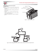
Resistance (ohm) testing:
• Set meter to proper scale.
• Be sure to zero the meter scale or identify the meter
burden by touching meter leads together. Meter bur-
den must be subtracted from final reading obtained.
• Be sure the meter leads touch source area only.
Prevent altering the reading by not allowing fingers
or body parts to touch meter leads or source during
reading.
• Be sure reading is taken when source is at 70ºF.
Readings taken at higher temperatures will increase
the reading. Conversely, readings taken at lower
temperatures will decrease the reading.
• Be sure to test directly at the source. Testing through
extended harnesses or cable extensions may increase
the reading.
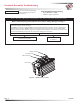
Dynamic/Live testing:
Definition: Connecting power and ground to a
component to test operation/function out of circuit.
1. Be sure to connect jumper leads directly and securely
to source contacts of the component being tested.
2. Be sure to make any connection to power and ground
at the power supply or battery source terminals. Do
not make connection at component source terminals
as that may create an arc and damage component
source terminals.