
Troubleshooting Guides

Page 3
TG29D
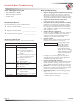
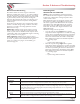
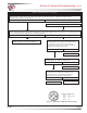
Figure 3 — N1601-1 thru -4, N1603-1/-2, and N1604-1/-2
Wiring Diagram
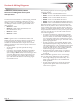
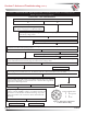
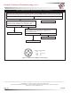
Figure 2 — N1604
Alternator and Regulator Terminals
Section A: Wiring Diagrams (CONT’D)
B+ connections on alternator
Interconnect
cable
Positive cables
from vehicle
B– connections on alternator
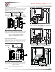
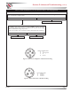
Figure 1 — N1601, N1602, and N1603
Alternator and Regulator Terminals
AC terminal
IGN terminal
B+ connections on alternator
Both positive terminals must be connected together at battery positive
potential, using interconnect cable and cable of suitable size as part
of vehicle cabling, when alternator is installed in vehicle and during
operation.
Interconnect
cable
Positive cables
from vehicle
B– connections on alternator
Both B– terminals must be connected to the vehicle’s common ground,
using interconnect cable and cable of suitable size as part of vehicle
cabling, when alternator is installed in vehicle and during operation.
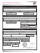
14V B+
terminal
(N3118 and
N3223 only)
Figure 4 — N1602-1, -2, -4, -5, -6 Wiring Diagram
•••
N3223 only—
J1939 connector
Figure 5 — N1602-3/-7 and N1603-3 Wiring Diagram
AC terminal
IGN terminal
Both positive terminals must be connected together at battery positive
potential, using interconnect cable and cable of suitable size as part
of vehicle cabling, when alternator is installed in vehicle and during
operation.
Both B– terminals must be connected to the vehicle’s common ground,
using interconnect cable and cable of suitable size as part of vehicle
cabling, when alternator is installed in vehicle and during operation.
Case ground: N1601, N1603
Isolated ground: N1604