
Troubleshooting Guides Owner manual

Page 6
TG0040A
Section 4: Advanced Troubleshooting
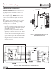
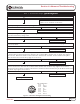
Figure 5 – Alternator-to-Regulator Harness Plug
PIN CONNECTIONS
Pin A F–
Pin B Phase 1
Pin C GND/B–
Pin D B+
Pin E Kelvin –
Pin F F+
Pin G Kelvin +
Pin H Phase 2
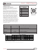
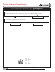
Chart 1 cont’d from Page 5 – No Alternator Output – Quick Diagnostic
Momentarily (1 sec.) jumper pin F in harness plug to alternator B+ terminal. Touch shaft with steel tool to
detect significant magnetism. Is shaft magnetized?
Ye s
No
Alternator is defective.
TT
TT
T
Regulator is defective.
TT
TT
T
TT
TT
T
Yes
No
Alternator is defective.
TT
TT
T
(CONT’D)
With DMM on resistance scale: Connect red lead to pin E in harness plug. Connect black lead to alternator
B+ terminal. Meter should read 0 ohms. Change pin E to pin G. Meter should read 0 ohms.