
Installation User Manual

C. E. Niehoff & Co. • 2021 Lee Street • Evanston, IL 60202 Tech Services Hotline 800-643-4633
II154E
Page 4 of 4
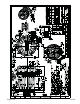
Figure 3 – Wiring Diagram
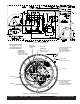
Figure 4 – Connections and Torque Values for Reference Only
Terminal A (wht)
Terminal B (wht w/blk)
Terminal C (wht w/red)
PHASE WIRE
CONNECTIONS:
Terminal F:
B–
Terminal D:
B+
Output cable
SEE STEP 1, PAGE 1
FIELD COIL
CONNECTION:
F– (wht)
FIELD COIL
CONNECTION:
D+
(wht w/ yellow: C192)
(wht w/red: C193)
All connections shown
(except where noted)
should be torqued to
2.9-3.9 Nm/26-35 lb. in.
Internal Earthing Bonding
M6 x 1 x 8mm screw
w/sems lockwasher
Torque to 14.9 Nm/132 lb. in.
SEE TABLE 1 and STEP 3
External Earthing Bonding
M6 x 1 x 10mm screw
w/sems lockwasher
Torque to 14.9 Nm/132 lb. in.
SEE TABLE 1, PAGE 1
Phase wire