
User Manual

GALEO
Illuminated RF Keypad
INSTALLATION MANUEL
GALEOR
Illuminated RF Keypad
INSTALLATION MANUAL
EN
9
cdvigroup.com
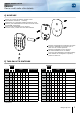
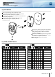
4] MOUNTING
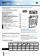
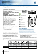
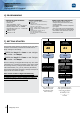
5] USER CODES TABLE
Channel
User A B Code Name
01
02
03
04
05
06
07
08
09
10
11
Channel
User A B Code Name
12
13
14
15
16
17
18
19
20
21
22
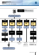
Drill the 2 mounting holes (drill bit Ø 5 mm
and 35 MM hole depth) and the hole wiring access.
Insert the 2 plastic anchors in the holes.
Stick the foam to sealed The GALEOR on the back side
of the base (Important).
Place the back plate of the GALEOR and screw
on the wall using the supplied (M4x30)
mounting screws.
Remove the plastic protection of the battery
and then mount the keypad on the back
plate, placing rst the top in the hooks
and then the bottom.
Fasten the GALEOR keypad to the back plate
by using the supplied (M4x10) Torx
®
screw
and T20 Torx
®
spanner hardware.
Place the screw cap at the bottom
of the keypad.