RS-990 P o w e r S o l u t i o n s ® LIBERTY P o SERIES w e r S o 1000 lutions Valve-regulated Lead Acid Batteries Installation and Operating Instructions COM
SAFETY PRECAUTIONS Only authorized and trained personnel familiar with standby battery installation, preparation, charging and maintenance should be permitted access to the battery. WARNING SHOCK HAZARD - DO NOT TOUCH UN-INSULATED BATTERY, CONNECTORS OR TERMINALS. BE SURE TO DISCHARGE STATIC ELECTRICITY FROM TOOLS AND TECHNICIAN BY TOUCHING A GROUNDED SURFACE IN THE VICINITY OF THE BATTERIES BUT AWAY FROM THE CELLS AND FLAME ARRESTERS.
FOR ADDITIONAL INFORMATION CONTACT: C&D Technologies, Inc. 1400 Union Meeting Road, PO Box 3053 Blue Bell, PA 19422-0858 215-619-2700 or 1-800-543-8630, Fax 215-619-7899 www.cdtechno.com FOR TECHNICAL or WARRANTY ASSISTANCE CONTACT: Technical Service Department located at: 1400 Union Meeting Road Blue Bell, PA 19422 215-619-2700 or 1-800-543-8630, Fax 215-619-7842 WARRANTY NOTICE This instruction manual is not a warranty.
INTRODUCTION The batteries referenced in this document are valve-regulated lead acid Liberty Series 1000 ®. They are constructed with pasted lead calcium plates with an absorbent glass mat and are valve-regulated. They are designed to provide long, reliable service life with minimal maintenance. The cells/units are shipped pre-assembled in 2-, 4-, 6- and 12-Volt modules to enable quick and easy installation.
RECOMMENDED TECHNICAL REFERENCES AND EXPERTISE These instructions assume a certain level of competence by the installer/user. The following recommended practices and codes contain relevant information, and should be consulted for safe handling, installation, testing and maintaining standby batteries. Applicable state and local codes must be followed. IEEE Std.
LIBERTY SERIES 1000 VALVE-REGULATED (SEALED) LEAD ACID BATTERIES INSTALLATION AND OPERATING INSTRUCTIONS TABLE OF CONTENTS PAGE INTRODUCTION. . . . . . . . . . . . . . . . . . . . . . . . . . . . . . . . . . . . . . . . . . . . . . . 2 Recombination: a more efficient design Recommended Practices, Technical Sources PART 1 RECEIVING AND INSTALLATION . . . . . . . . . . . . . . . . . . . . . . . . . . . . . . . . . 6 SECTION 1 - RECEIVING . . . . . . . . . . . . . . . . . . . . . . . . . . . . . . . . . . .
SECTION 2 - BATTERY OPERATION . . . . . . . . . . . . . . . . . . . . . . . . . . . . . 18 2.1 2.2 2.3 2.4 Float charging Equalizing charge Over-voltage Voltmeter calibration SECTION 3 - GENERAL INFORMATION AND MAINTENANCE. . . . . . . . . 20 3.1 3.2 3.3 3.4 3.5 3.6 3.7 3.8 3.
PART 1 RECEIVING AND INSTALLATION SECTION 1 - RECEIVING 1.1 General Information and Precautions This battery is designed for industrial use only and is not intended for application in vehicular starting, lighting, and ignition, and/or operation of portable tools and appliances. Use only in accordance with manufacturer’s written instructions.
nent packing list. This verified list should show both the name of the packer, as well as the quantities of items checked off by the receiver. Send the list to: C&D Technologies, Inc. Attn.: Customer Service 1400 Union Meeting Road Blue Bell, PA 19422 SECTION 2 - STORAGE and SHELF LIFE 2.1 Storage of VRLA (valve regulated lead acid) Batteries Store batteries indoors, preferably at 77°F (25°C) or in a cool 20°F to 90°F (-7°C to 32°C), dry location and place on charge by the date found on the battery carton.
acid batteries are warranted against defects in materials or manufacturing or both. To keep the warranty in effect, you must place the units on charge by the date stamped on the shipping carton when stored at 77°F (25°C). If storage beyond this time is required or storage temperature is in excess of 77°F (25°C), monitor battery voltage at monthly intervals, if possible. A convenient measurement technique is to read the open circuit voltage. If the open circuit voltage drops below 2.
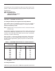
TABLE 2 - BATTERY SPECIFICATIONS (Characteristics subject to change without notice. Refer to current specifications 12-373) Model Nominal voltage Number of cells in module LS 12-25* 12 Volts 6/unit LS 6-50* 6 Volts 3/unit LS 12-55 12 Volts 6/unit LS 12-80 12 Volts 6/unit Rated 8 hr. Capacity (Amperehours to 1.75 Vpc) Rated 15-min. capacity (kiloWatts to 1.67 Vpc) Internal resistance/cell Short circuit current Unit height 25 Ah to 10.50 Volts 0.092 50 Ah to 5.25 Volts 0.185 52 Ah to 10.50 Volts 0.
TABLE 2 (CONTINUED) Model Nominal voltage Number of cells in module Rated 8 hr. capacity (Amperehours to 1.75 Vpc) Rated 15-min capacity (kiloWatts to 1.
VRLA batteries when subjected to extreme overcharge (above the recombinant ability of the cell) can release hydrogen gas at a maximum rate of 0.000269 cubic feet per minute per ampere of charging current at 77°F (25°C) at atmospheric pressure. 3.3 Rack Assemblies Liberty Series 1000 batteries may be installed in a variety of mounting assemblies • Modular Rack assembly (Figure 3.1) - battery units may be assembled in a floor mounted module or rack. One modular rack available from C&D Technologies, Inc.
SECTION 4 - ELECTRICAL CONNECTIONS WARNING • Always use protective insulating equipment, such as gloves, shoes and eye and face protection. Wrenches and other tools must be insulated. • Observe local, state, and national electric codes at all times. • Always work with the battery ungrounded. Battery ground connections, if required, should be made last. • To avoid working with high voltages, break the battery down into convenient lower-voltage modules, i.e., equal to or less than 48-Volts.
CAUTION Do not use steel brushes, steel wool, sandpaper or emery cloth to clean surfaces, as these will damage the plating. Do not use cleaning solvents. Solvents can cause crazing or cracking of the plastic cell containers or covers. Use of solvents will void the warranty. 4. Attach intercell connectors or cable/lugs from the positive post of one unit to the negative post of the next cell or unit for series connection.
CAUTION Use extreme care when installing connectors; maintain a firm grasp on each connector as it is being installed, to prevent it from dropping and potentially causing a short circuit. Note: Over-torquing can damage the post seal causing electrolyte leakage. 4.4 Checking connection integrity • Check once again that all units are connected positive terminals to negative terminals. Measure the battery voltage with a digital voltmeter. The voltage should be approximately 2.
resistance for each battery. A wide variation in circuit resistance can result in unbalanced discharging and charging of cells. As a consequence this can produce unequal float voltages of the connected cells and individual strings can sustain a loss of performance and capacity, resulting in higher loads on the other parallel strings with lower cable (circuit) resistance.
PART 2 CHARGING AND OPERATION OF BATTERY SECTION 1 - CHARGING 1.1 General Information and Precautions To safely charge the Liberty Series 1000 batteries and avoid damaging the battery and/or connected equipment, observe the following: • Use only direct current for charging. AC ripple current from charger must not exceed 5 percent of the 8-hour (Ampere-hour) rating of the battery. • Be sure charger is turned off before making electrical connections between the battery and system.
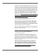
TABLE 3 CHARGE VOLTAGES FOR LIBERTY SERIES 1000 CELLS CHARGE VOLTAGES AT 77°F (25°C) Cell Type Open Circuit (Vpc) Minimum Cell Voltage (Vpc) Float Voltage (Vpc) Initial Charge Voltage (Vpc) Typical Charging Time for Initial Charge All Liberty Series 1000® 2.15 2.20 2.26 +/- 0.01 2.33 +/- 0.02 12 - 16 Hours Note 1: 1 - Applies to average cell voltage. Battery voltage should be set at average cell voltage multiplied by the number of cells in unit or string.
minimum of 72 hours before any load is placed on the system. The battery is now considered fully charged and is ready for either initial acceptance testing or regular service. Use only direct current for charging. AC ripple current from charger must not exceed 5 percent of the 8-hour (Ampere-hour) rating of the battery. 1.
For optimum service, adjust the power supply to the float voltages shown in Table 3. If the power supply is intermittent or more frequent discharges are anticipated, use a higher value recommended voltage setting. Note: For locations that exhibit frequent temperature variations it is recommended that temperature compensated rectifiers be used that adjust the voltage in accordance with sub-sections 3.4 and 3.5 of Section 3. 2.
To avoid over-voltage, periodically check battery voltage with a calibrated digital voltmeter. If an over-voltage is recorded, check and readjust the rectifier and/or panel meter calibration as necessary. Place the battery at the recommended float charging voltage as soon as possible. Restoring the proper float voltage will preclude further damage caused by charging at an over-voltage but it cannot reverse damage that has already been sustained by the battery.
3.2 Capacity and testing Batteries are rated in Ampere-hours or kiloWatts on their ability to deliver a certain number of amperes or power, respectively, to the load for a specified amount of time before cell voltages drop to a final design potential. It is important to understand that the ampere-hour capacity or kiloWatts of a cell or battery depends upon the rate at which it is discharged. Consult C&D Technologies specification sheet 12-373 for the ratings of various cell types.
When the voltages of individual cells are lower than normal, it is possible to conclude that insufficient charging has occurred. The following are possible causes of cell voltage variations: • Panel voltmeter reading high - This results in a low float voltage. Re-calibrate the panel voltmeter. • Poor intercell/inter-unit or terminal connections - If any connection is found to be higher than 20% of the initial installation values, disassemble and clean contact surfaces and reassemble.
If continuous adjustment of the battery plant charger voltage relative to ambient temperature is impractical, it is recommended the appropriate fixed float voltage setting of Table 4 is used. At temperatures below 77°F (25°C), battery capacity will be reduced by approximately 0.5 percent per degree Fahrenheit. Caution must be exercised when operating or storing batteries at low temperature because of the possibility of electrolyte freezing.
3.6 Cleaning cell covers • Cell covers can be dusted with a clean cloth or clean dry paintbrush. • Cell covers may also be cleaned with clear water and a small amount of baking soda and dried after cleaning. • If residual acid appears on the cover surfaces it may be neutralized with a solution of one pound baking soda and one gallon of clear water. Rinse with water following neutralization and air dry. CAUTION Never use solvents other than water to clean battery containers.
completely recharge the battery and take a set of voltage readings, recording them for future reference if the readings are satisfactory. Provide remedial action or an equalize charge if necessary. Do not discharge a battery below the design final voltage. Remedial action may be required if the battery was discharged below its final design voltage. Very deep discharges can, without an immediate recharge, completely deplete the electrolyte and cause hydration.
PART 3 TROUBLE-SHOOTING, AVOIDING BATTERY DEGRADATION AND RECOGNIZING PROBLEMS SECTION 1 - HOW TO AVOID BATTERY DEGRADATION 1.1 General Information and Precautions Properly maintained and charged, Liberty Series 1000 batteries will provide many years of trouble-free service. However, despite their inherent dependability, failure to operate and maintain them correctly can lead to damage, shortened service life or cause loss of service.
CAUTION RECHARGE BATTERIES AS SOON AS POSSIBLE AFTER AN EMERGENCY DISCHARGE. Failure to recharge batteries immediately after emergency discharge may lead to sulfation or, in the case of deep discharge, to complete battery failure due to hydration. If recharging at equalize voltage is impractical, recharge at float voltage. 1.
the affected cells may become sulfated and require corrective action. 1.6 Parallel battery strings When strings of batteries of equal voltage are connected in parallel, the overall capacity is equal to the sum of the capacities of the individual strings. When paralleling valve-regulated batteries is necessary, the external circuit resistance must be matched for each battery. A large variation between battery string resistance can result in unbalanced discharge (i.e.
14-312 MATERIAL SAFETY DATA SHEET SECTION I: CHEMICAL PRODUCT AND COMPANY IDENTIFICATION PRODUCT IDENTITY: Sealed, Lead-Calcium Battery MANUFACTURER NAME: C & D Technologies, Inc ADDRESS: 1400 Union Meeting Road P. O. Box 3053 Blue Bell, PA 19422-0858 TELEPHONE: (215) 619-2700 EMERGENCY: (610) 828-9309 24 HOUR EMERGENCY TELEPHONE: (CHEM TEL) 1-800-255-3924 CDID: LIBERTY 1000 SERIES LS 12-25, 6-50, 12-100, 6-200, 4-300 & 2-600 LFA 12-100.
14-312 handling.
14-312 Boiling Point: N/A Vapor Density: (air=1): >1 Evaporation Rate (water=1): N/A Boiling Point: N/A Specific Gravity (contained in battery): 1.300+/-.010 Vapor Density: (air=1): >1 Evaporation Rate (water=1): N/A Specific Gravity (contained in battery): 1.300+/-.010 Vapor Pressure: N/A Melting Point: N/A Solubility in water: N/A Vapor Pressure: N/A Melting Point: N/A Solubility in water: N/A 14-312 SECTION X: STABILITY AND REACTIVITY STABILITY: This battery and contents are stable.
14-332 MATERIAL SAFETY DATA SHEET SECTION I: CHEMICAL PRODUCT AND COMPANY IDENTIFICATION PRODUCT IDENTITY: Sealed, Lead-Calcium Battery CDID: LIBERTY SERIES LS 12-55, 12-80 only; FA 12-125, FAM 12-125 EMERGENCY: (610) 828-9309 24 HOUR EMERGENCY TELEPHONE: (CHEM TEL) 1-800-255-3924 MANUFACTURER NAME: C & D Technologies, Inc. ADDRESS: 1400 Union Meeting Road P. O.
14-332 SECTION IV: FIRST AID MEASURES x x x EMERGENCY AND FIRST AID PROCEDURES: SKIN / EYES INGESTION Flush with water for 15 minutes x Do not induce vomiting Remove contaminated clothing x Drink large quantities of milk or water x Give CPR if breathing has stopped If irritation continues, seek medical attention.
14-332 Appearance / Odor: colorless, oily fluid, acrid odor when hot. Boiling Point: N/A SECTION X: STABILITY AND REACTIVITY STABILITY: This battery and contents are stable. CONDITIONS TO AVOID: Overheating, overcharging which result in acid mist / hydrogen generation. INCOMPATIBILITY (materials to avoid): Strong alkaline materials, conductive metals, organic solvents, sparks or open flame.
Appendix B - WARRANTY PROVISIONS FOR LIBERTY SERIES 1000 BATTERIES C&D Technologies valve regulated lead-acid batteries are warranted against defects in materials or manufacturing or both from C&D factory when operated in full float and when stored at 77°F (25°C). Refer to specific warranty certificates for your Liberty 1000 model for float or UPS operation and for storage at other temperatures.
Appendix C - VALVE-REGULATED LEAD ACID BATTERY AND CHARGER INSPECTION REPORT A sample inspection report form is provided in the following pages of this manual and is referred to as RS-1511. This form should be used to record appropriate battery, charger and related system information at timely events such as: • Initial installation of the battery at which time open circuit voltage of all cells should be recorded.
P o w e r TECHNICAL SERVICES DEPARTMENT 1400 UNION MEETING ROAD BLUE BELL, PA 19422 S o l u t i o n s Inspection by:___________________ Power S o Date l u t of i oInspection:_______________ ns COM LIBERTY® SERIES 1000 BATTERY AND CHARGER A Division of C&D Technologies, Inc. INSPECTION REPORT User’s Name: Authorized Site Contact: A Division of C&D Technologies, Inc. Installation Location: Phone No.: Other: A Division of C&D Technologies, Inc.
BATTERY CHARGE STATUS BATTERY BUS VOLTAGE ■ OPEN CIRCUIT __________Vdc Location: Model: Cell No. 38 Volts +2.000 Serial No. Internal Cell Connection Conductance Resistance /Impedance/ Resistance ■ FLOAT __________Vdc ■ EQUALIZE _________Vdc Date: Cell No. Volts +2.000 Internal Cell Serial Connection Conductance No.
NOTES 39
NOTES 40
POWER SYSTEMS DIVISION 1400 UNION MEETING RD. P.O. BOX 3053 BLUE BELL, PA 19422-0858 USA (215) 619-2700 • FAX (215) 619-7899 (800) 543-8630 www.cdpowercom.com Any data, descriptions or specifications presented herein are subject to revision by C&D Technologies, Inc. without notice. While such information is believed to be accurate as indicated herein, C&D Technologies, Inc.