
Instructions


9
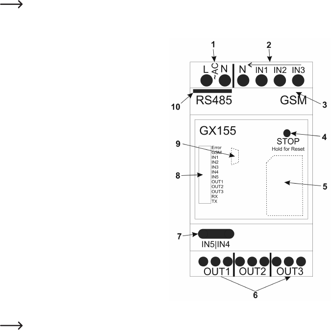
b) Casing Overview
Theproductisexplainedstepbystepinthefollowingchapters.
Toensurethatthedeviceissetupcorrectly,makesuretoreadtheseoperatinginstructions,includingthe
safetyinstructions,completelyandattentivelybeforeuse.
Theproductisexplainedstepbystepinthefollowingillustration:
1 Supplyvoltage:230V/AC
2 IN1toIN3:Switchinginputs230V
3 Connection GSM aerial
4 Stop/resetbutton
5 Position of the SIM card (under the cover)
6 OUT1toOUT3:Switchingrelay,switcher
7 IN4andIN5:Switchinginputs32V
8 Status LEDs
a) ERROR
b) GSM
c) IN1 to IN3
d) IN4 and IN5
e)OUT1toOUT3
f) RXandTX
9 Position of the mini USB socket (under the cover)
10 RS485 interface
IN1 to IN5 are lit automatically when the input voltage at the input has exceeded the threshold value.
OUT1toOUT3lightupautomaticallywhenthecorrespondingrelayisswitched.
RXandTXashautomaticallyatRS485communication.
Openthefrontcoveronleft,right,upperorlowerside.