
User manual

C-COM Satellite Systems Inc. Page 30 of 128
iNetVu™ 7000 Controller User Manual
Revision 1.19
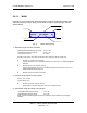
6.6.1.2. EL
Displays real-time current drawn and speed settings for the elevation motor, as well as
real-time elevation angle and limits, offset, window size, and Elevation adjustment gap.
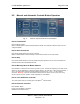
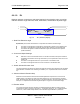
Fig. 15: “EL” (Elevation) Display
1 – Real-Time Elevation Angle
E (Elevation) The number value after the “E” represents the real time elevation angle.
D The letter “D” will appear to indicate Down Limit has been reached on the elevation axis
U The letter “U” will appear to indicate UP Limit has been reached on the elevation axis
S The letter S will appear to indicate the Elevation angle has reached the stow position
(Antenna Stowed).
2 – Current and Speed Settings
I/S Real-Time current of the elevation motor is to the left of the dash, and speed constant of
the elevation movement is to the right of the dash (i.e. 0-6 represents current of 0 at a set
speed of 6).
U The letter “U” will appear if there is an up movement on the elevation axis.
D The letter “D” will appear if there is a down movement on the elevation axis.
3 - Search Window Elevation Limit
This value represents the amount of degrees the antenna will point above and below the calculated
target elevation coordinate when searching for satellite. (S: 5 – implies elevation search window is
5º)
4 – Advanced Search Elevation Gap
Parameter used to determine the small incremental adjustments required for a more accurate
satellite search. It represents the value used while searching on an incline surface on elevation
angle. Decreasing this value will add accuracy to the Search Window, but will increase the search
time. (AD: 3 – implies that the elevation angle will adjust if 3º gap from the calculated angle)
5 - Elevation Offset
The number of degrees at which the iNetVu™ Mobile Software will offset the reading from the
Inclinometer in order to produce an accurate (+/- 2°) Elevation Angle (e.g. O: 31 implies elevation
offset of 31). These values initially default, and are set after target calibration is performed.
E0.0 D U S I/S:0-6 U D
S: 5 AD: 3 O: 31
1 2
3 5
4