Instruction Manual 3-D Flow Chamber Device
T A B L E O F C O N T E N T S Section 1: General Information 1.1 Flow rate chart. . . . . . . . . . . . . . . . . . . . . . . . . . . . 3 1.2. References . . . . . . . . . . . . . . . . . . . . . . . . . . . . . 3 1.3 System Overview. . . . . . . . . . . . . . . . . . . . . . . . . . . 4 1.4. System Contents. . . . . . . . . . . . . . . . . . .
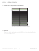
SECTION 1 1.1 GENERAL INFORMATION Flow rate chart for Pump Controller for Quick Reference ml/min 0.2 0.3 0.4 0.5 0.6 0.7 0.8 0.9 1 2 3 5 10 20 30 44 dyn/cm2 0.7 1 1.3 1.6 1.9 2.3 2.6 2.9 3.3 6.6 9.8 16.3 35.7 71.6 107 157.4 44ml/min is the maximum flow rate for the Pump Controller. 1.2 References Please go to this link: http://www.jove.com/video/50959/a-novel-three-dimensional-flow-chamber-device-to-study-chemokine 3-D Flow Chamber Device Instructions April 2014 3 www.cbsscientific.
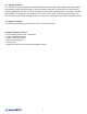
1.3 System Overview The 3-D Flow Chamber Device is a specialized laminar flow chamber that enables the unique ability to quantitate cellular motility through a semi-permeable membrane in the presence of shear stress. Relevant applications for the 3-D Flow Chamber Device include transmigration, chemotaxis, vascular permeability, and complex in vitro modeling of 3D cell cultures such as the blood brain barrier.
Pump Controller Respirator (Bubble Trap) Carrying Tray (optional) Flow Cell (disassembledl) Reagent Reservoir (3x) Lower Inserts Upper Inserts 3-D Flow Chamber Device Instructions April 2014 5 www.cbsscientific.
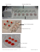
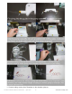
SECTION 2 CELL CULTURE ON UPPER & LOWER INSERTS 2.1. Coat the membrane disk with the relevant substrate to support cell adhesion a. Using aseptic technique (sterile forceps) place the dry membrane disk on a dry sterile petri dish The top membrane is positioned so that the membrane support (clear ring) is on the bottom and the membrane is facing up. The bottom membrane is positioned so that the membrane support is facing up – the membrane disk will look like a little cup. b.
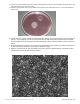
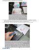
a. Remove any liquid remaining from the coating and dispense the cells onto the membrane as shown above. The liquid will bead up as it did when coating. b. Place the covered petri dish in the incubator and incubate for the desired amount time – most cells will attach within 1 hour. c. Fill the dish with medium so that the membranes are floating.
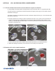
SECTION 3 FLOW CHAMBER SET-UP & USE 3.1 Preparation a. Assemble all of the needed components in the area where you will set up the chamber (the chamber, the tubing, forceps, pump, respirator, the clamps, and connectors) b. Prepare chemokines, buffers, etc. c. If you are going to perform your experiments at 37˚C, pre-warm all the media to avoid spontaneous bubble formation. 3.
c. Connect tubing coming from Respirator to the chamber (above). 3-D Flow Chamber Device Instructions April 2014 9 www.cbsscientific.
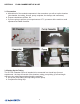
3.3 Priming the Tubing in Preparation for an Experiment. a. Prepare a 50 ml tube with your buffer of interest place the tubing (right side, not the Respirator side) into the tube. Run the pump so that it is pumping in the direction of the Respirator. A flow rate of ~2ml/min is a good starting point. Make sure the pinch clamp is closed on the Respirator side. b. Fill the Respirator, cover it and release the pinch clamp when ready to connect to 3D chamber.
3.4. Filling the Reservoirs and Assembling the 3D Chamber. a. If you are using 2 membranes as a sandwich fill the reservoir with ~800 ul of chemokine or buffer. If you are using the single top membrane fill the chamber with ~1.5ml of chemokine or buffer. b. Work quickly! If using the double membrane, first pop the membranes together and then lay them into the reservoir. If using a single membrane, lay it over the buffer using forceps.
c. Close the chamber.
d. Start the pump (direction towards the respirator) - 1-2 mls/min. Tilt the chamber slightly upwards to facilitate bubble clearance from the chamber. You also may tap it lightly to dislodge any bubbles. Once buffer is coming out the other side of the chamber attach the tubing to close the loop. e. Reduce the pump speed to desired level for experiment (see appendix). 3.5. Introducing Circulating Cells to the Flow Chamber without Disrupting the Flow. a. Prepare cells to desired density.
3.6. How to Recover Cells from the Chamber At the end of the experiment, if desired cells can be collected from the reservoirs and the sandwich space created by the membranes. Before stopping the pump and terminating the experiment – be sure to have tubes ready for cells from reservoirs and have clean petri dishes to take the membrane sandwiches apart. a. First stop the pump. Close both pinch valves. b. Working quickly – take chamber apart on a paper towel or absorbent mat. Remove excess chamber liquid.
3-D Flow Chamber Device Instructions April 2014 15 www.cbsscientific.
3.7. Cleaning the System After Use. • The membranes are meant to be disposed of after use according to the biosafety guidelines of your institute. • The durable parts of the system (chamber, tubing, connectors, Respirator, etc...) can be decontaminated by placing them in a solution of 10% bleach for 20 minutes. Tubing can either be disposed of outright or flushed with a bleach solution if re-use is desired. Avoid using alcohols, uv or other harsh cleaners as they may adversely affect the surfaces.
SECTION 4 ADDITIONAL TIPS AND TROUBLESHOOTING 4.1. Media Considerations • All fluids should be equilibrated to temperature to avoid bubble formation. • Maintenance of pH by CO2 buffering must be achieved by placing the respirator into a Tissue culture incubator with a loose fitting Petri dish cover on the top of it allowing gas exchange into the system.
3-D Flow Chamber Device Instructions April 2014 19 www.cbsscientific.
3-D Flow Chamber Device Instructions April 2014 21 www.cbsscientific.
The tubing loop diameter controls the range of flow rates for the system. The range of flow rates per tube diameter (mm) is shown below. The system includes tube loops with diameters of both 1.22 mm and 1.52 mm to enable flow rates from 0.079 ml/min to 12 ml/min. The relationship of flow rate to shear is shown in the next section.
Flow rate chart for Pump Controller ml/min dyn/cm2 0.2 0.7 0.3 1 0.4 1.3 0.5 1.6 0.6 1.9 0.7 2.3 0.8 2.6 0.9 2.9 1 3.3 2 6.6 3 9.8 5 16.3 10 35.7 20 71.6 30 107 44 157.4 44ml/min is the maximum flow rate for the Pump Controller. 3-D Flow Chamber Device Instructions April 2014 23 www.cbsscientific.
CONTACT INFORMATION Online Ordering www.cbsscientific.com Telephone Local and International: 858-755-4959 Toll Free: 800-243-4959 Sales E-mail Address sales@cbssci.com Technical Service E-mail Address technicalservice@cbssci.com Mailing Address P.O.