INSTRUCTION MANUAL Cipher Genetic Analysis System DTSK-2001-110 DTSK-2001-220 DTSK-2401-110 DTSK-2401-220 One System that Detects Mutations and Polymorphisms 4 different ways: 1) DGGE - Denaturing Gradient Gel Electrophoresis 2) TTGE - Temporal Temperature Gradient Electrophoresis 3) SSCP - Single Strand Conformational Polymorphisms 4) CDGE - Constant Denaturant Gel Electrophoresis 1 www.cbsscientific.
TABLE OF CONTENTS Important User Information 3-4 Section 1 1.1 1.2 1.3 General Information Introduction Specifications Safety 5 6 6 Section 2 2.1 2.2 Description of parts Unpacking Components/Assembly 7 7 Instructions for Use Unit Set-up and Unpacking Heater/Stirrer General Set-Up Heater/Stirrer Programming 3.3.1 Setting Operational Parameters and Functions 3.3.2 Entering/Modifying a Temperature Program 3.3.
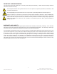
IMPORTANT USER INFORMATION This Instruction Manual will explain how to use this product safely and effectively. Please read and carefully follow the instruction manual in its entirety. The triangle/exclamation mark symbol alerts the user of the product to important operational, maintenance, and/ or warranty requirements. The triangle/lighting bolt symbol alerts the user of the product to potentially hazardous electrical exposure.
ESPAÑOL FRANÇAIS INFORMATION IMPORTANTE À L’USAGE DES UTILISATEURS Le présent manuel d’utilisation explique la manière de se servir efficacement du produit en conditions de sécurité. Il est recommandé de soigneusement lire la totalité du manuel, avec ses consignes et ses instructions. El símbolo del triángulo con exclamación llama la atención del usuario a requisitos importantes para el uso y mantenimiento del producto, así como para la validez de la garantía.
SECTION 1 General Information 1.1 Introduction DESCRIPTION The Cipher Genetic Analysis Systems (DTSK-2001 and DTSK-2401) allow the researcher to choose which technique is most applicable to their investigation. Both DGGE and TTGE rely on establishing a gradient of either solvent (Urea/Formamide) or temperature in which the target fragments will undergo conformational transition (melt).
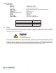
1.2 Specifications Constructions DTSK Tank Sodalime glass, Kydex DTSK Lid Sodalime glass, Kydex Electrodes Platinum wire .012” diameter Power cords FR Polypropylene/Silicone, rated 7500V, 200mA, 65° C DTSK Cassette Acrylic Cooling Coil brass, copper, PVC Heater/Stirrer Buffer Cycler Stainless steel Combs Teflon/ Acrylic Spacers Proprietary Glass Plates Sodalime or Borosilicate Gradient Maker Acrylic, teflon, stainless steel DTSK-2401 Gel Size 17.
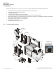
SECTION 2 Description of Parts 2.1 Unpacking Please verify that your Cipher Genetic Analysis System comes complete with the following components: • • • • • • • • • 2.2 Lower Reservoir/Glass tank/safety interlock/ with 2 black leads inside lid Heater/Stirrer/By-pass pump/Cooling Coil Two Dual Gel cassettes 1 Gradient maker, 20mls per side, Cat.
SECTION 3 Instructions for Use 3.1 Unit Set-up and Unpacking Instructions 1. Unpack lower reservoir and place on level surface in an approved location. 2. WARNING: Do NOT turn on Heater/Stirrer until tank has been filled with buffer. The MINIMUM buffer volume for heating is 23 liters. Turning Heater/Stirrer on with less than 23 liters of buffer will damage the heating coil, and void warranty. If running two dual cassettes, the buffer volume is 24 liters. 3.
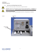
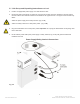
3.1 Unit Set-up and Unpacking Instructions-continued 4. Position an appropriate power supply on a shelf above the tank. 5. Fill the tank with running buffer. To obtain the correct level of buffer, place the cassettes in the tank and fill the tank until the level of buffer reaches the underside of the upper reservoir. The upper reservoir holds only 50mls. 6. Attach the power supply to the safety interlock. (Fig 3-2-A) 7. Attach the safety interlock to a wall (mains) outlet. (Fig 3-2-B) 8.
3.2 Heater/Stirrer Set-Up and Programming 3.2a General Information Model Type Heat Only Immersion Circulator Temperature Range Reservoir Capacity Amps @ 120V, 60Hz Amps @ 240V, 50Hz Ambient +5°C to 200°C* N/A 11A 9.7A Circulator Pump Pump speed is selected via the Main Menu. The MINIMUM setting is used for DGGE applications. MAXIMUM is recommended where temperature varies frequently and there is a need for fast recovery or when pumping to multiple external units.
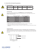
3.2 Heater/Stirrer Set-Up and Programming – continued 3.2b Front and Rear Panels 15 2 8 9 1 3 16 10 14 7 4 5 17 6 11 13 12 Front View Rear View 1. Select / Set Knob 10. Identification Label 2. LCD Display 11. Reservoir Purge 3. Safety Set Indicator Knob 12. Pump Inlet (Do NOT open) 4. Safety Set Reset Button 13. Pump Outlet (Do NOT open) 5. Timer Button 14. AC Input 6. Escape Button 15. External Probe Connection2 7. Power On/Off Button 16. RS232 Interface 8.
3.2 Heater/Stirrer Set-Up and Programming – continued 3.2c Specifications Temperature Stability1 ±0.01°C Controller / RS232 Yes External Temperature Probe Functional on Programmable models / optional external probe required Not functional on Digital models Readout Accuracy Graphic LCD, °C or °F, ±0.25°C Heater 1100W – 115V, Pressure Flow Rate 15.
3.2 Heater/Stirrer Set-Up and Programming – continued 3.2d Circulator Location Locate the Circulator on a level surface, free from drafts and out of direct sunlight. Do not place it where corrosive fumes, excessive moisture, high room temperatures, or excessive dust are present. Refrigerating/Heating Circulators must be a minimum of four inches (102mm) away from walls or vertical surfaces so air flow around the unit is not restricted.
3.2 Heater/Stirrer Set-Up and Programming – continued 3.2h Power An IEC power cord is provided with the Circulator. This power cord should be plugged into the IEC receptacle on the rear of the Controller and then plugged into a properly grounded outlet. Make sure that the power outlet is the same voltage and frequency indicated on the identification label on the back of the Controller. The use of an extension cord is not recommended.
3.2 Heater/Stirrer Set-Up and Programming – continued The pump will begin operating; the display will show the current bath temperature and the set point temperature (Setpoint). If an external probe (Programmable Controllers only) is connected, both the internal and external bath temperatures will be displayed. The temperature probe selected to control bath temperature (internal or external) will be displayed in larger numerals.
3.2 Heater/Stirrer Set-Up and Programming – continued 3.2m Menu Navigation Main Menu — To view the Main Menu items, rotate the Select/Set Knob. Continue turning the Select/Set Knob to scroll through the Main Menu displays. To begin programming or view the options available in a Main Menu item, press the Select/Set Knob. The first available sub-menu item (or the last item in that sub-menu which was selected) will be highlighted like THIS To de-select an item, press the ESC Button.
3.2 Heater/Stirrer Set-Up and Programming – continued 3.2n Menu Structure Main Menu Item Associated Sub-Menu Items Choices / Ranges / Comments Timer Set Beep 00:00:00 to 99:59:59 On or Off Program1 Program # Program Steps Program Loops Step # Step Setpoint Minutes/Seconds View Profile 1 to 10 1 to 50 1 to 99 1 to 50 –50° to 200°C (-50° to 392°F) 0 second to 999 minutes, 59 seconds Displays temperature profile of program.
3.2 Heater/Stirrer Set-Up and Programming – continued 3.2o Fluid Type Located in the Fluid Type screen are two adjustable parameters: Specific Heat and Volume. By adjusting the Specific Heat you will be optimizing the circulator’s temperature control based on the fluid being used. The table below lists a few common fluids. You can also refer to the MSDS sheets for your specific fluid. The other parameter, Volume, is strictly for diagnostic purposes and does not affect the performance of the unit.
.2 Heater/Stirrer Set-Up and Programming – continued 3.2r Setting Preferences The Preferences sub-menu allows you program global preferences regarding instrument operation. Readout — This is the number of decimal places to which temperatures will be displayed (0, 1, or 2). Units — This is the unit in which temperatures will be displayed (°C or °F) Sound — This is the volume level for the unit’s audible signal. When it is selected, the volume of the audible signal changes as the Select/Set Knob is rotated.
3.2 Heater/Stirrer Set-Up and Programming – continued 3.2s Setting High/Low Temperature and Alarms The Limits/Alarms sub-menu allows you to establish temperatures at which either power to the temperature control components (heater/condenser) will be disconnected (Limits) or which Controller’s audible alarm will sound (Alarms). Limit High Temperature — This feature provides additional safety and protection by allowing a selectable upper temperature limit set point.
3.2 Heater/Stirrer Set-Up and Programming – continued To clear an Alarm Low warning, correct the problem or decrease the Alarm Low temperature value. Limit Low Temperature — This feature provides additional safety and protection by allowing a selectable lower temperature limit set point. If you attempt to enter a set point value that exceeds the Limit Low value, the audible alarm will sound and a Warning message will flash on the display when the Limit Low value is reached.
3.2 Heater/Stirrer Set-Up and Programming – continued 3.2u Displaying the Bath Temperature Trend The Controller can store up to 48 hours of bath temperature data. The data can be viewed by selecting Temperature Trend from the Main Menu. To view the temperature trend data, rotate the Select/Set Knob until the Temperature Trend display appears, showing the most recent temperature data. The time period which the displayed trend line covers appears in the lower left corner of the display.
3.2 Heater/Stirrer Set-Up and Programming – continued 3.2v Selecting the Temperature Probe (Internal or External) The Probe sub-menu allows you to designate whether to control temperature using the internal bath temperature or the fluid temperature at an external device. It is available on the Programmable Controller only and requires the use of an optional external temperature probe.
3.2 Heater/Stirrer Set-Up – continued 3.2w Setting the Display Contrast and Timeout Display Contrast and Display Timeout appear as sub-menu items under Instrument in the Main Menu. These menu items allow you to change the readability of the LCD and set the length of time, which can pass without menu activity before the display will revert to the main operational display. NOTE: When Contrast is selected, the display contrast will change as the Select/Set Knob is rotated.
3.3 Heater/Stirrer Programming 3.3.1 Setting Operational Parameters and Functions All operational parameters and functions are programmed and controlled via the Controller’s software settings. Most are user-adjustable and easily accessed via the Main Menu. The Main Menu is accessed by rotating the Select/Set Knob. A particular Main Menu item is selected by pressing the Select/Set Knob when that item is highlighted. 1.
3.3 Heater/Stirrer Programming- con’t. 3.3.2 Entering/Modifying a Temperature Program NOTE: This function is available on Programmable Controllers only. See Writing a Temperature Program below for information on creating a time/temperature profile. This menu selection allows you to program and store up to ten individual time/temperature profiles. Each program can have up to 50 steps and 99 program loops. Once a program has been entered, any portion of it may be modified.
3.3 Heater/Stirrer Programming- con’t. Once the temperature set point has been entered, press the Select/Set Knob to advance to the time (minutes/ seconds) field. Time information is entered the same way as the temperature set point information. When you press the Select/Set Knob to accept the time displayed time information, the highlighted box will automatically advance to the set point temperature field associated with the next step of the program.
3.3 Heater/Stirrer Programming- con’t. Programming Examples Example A Initial Bath Temperature = 25°C Program Priority = Temperature Desired Profile: Cool bath temperature to 20°C and hold it there for 25 minutes. Increase bath temperature to 30°C and hold it there for 15 minutes. Increase bath temperature to 50°C over a 45 minutes period. Decrease bath temperature to 5°C and hold.
3.3 Heater/Stirrer Programming- con’t. Example B Initial Bath Temperature = 25°C Program Priority = Temperature Desired Profile: Cool bath temperature to 20°C and hold it there for 10 minutes. Decrease bath temperature to 10°C over 15 minutes. Hold bath temperature at 10°C for 15 minutes. Increase bath temperature to 50°C over a 1-hour period.
3.3 Heater/Stirrer Programming- con’t. Example C Initial Bath Temperature = 25°C Program Priority = Temperature Desired Profile: Cool bath temperature to 20°C as fast as possible. Increase bath temperature to 55°C as fast as possible. Repeat 7 times.
3.3 Heater/Stirrer Programming- con’t. 3.3.3 Running a Temperature Program NOTE: This function is available on Programmable Controllers only. The Programmable Controller can store up to 10 user-defined time/temperature programs, which can later be run with just a few simple commands. See Entering/Modifying a Temperature Program above for more information. Programs may be run using either a Time- or Temperature-based priority.
3.3 Heater/Stirrer Programming- con’t. If a program is stopped or paused, the Controller will control temperature using the set point value that was active when the program was interrupted. NOTE: If you select the Temperature Trend display while running a program, that display will remain on screen until the ESC Button is pressed. End of Program — Once the selected program has run, “Completed” will appear in the lower left of the Run Program display.
3.3 Heater/Stirrer Programming – continued 3.3.
Message Display Description Action Required Analog to Digital conversion fault Instrument Failure — Power to heater, compressor, and pump automatically disconnected. Contact supplier. Internal temperature probe fault Probe Failure — Power to heater, compressor, and pump automatically disconnected. Contact supplier. Internal temperature probe fault Probe Failure — Power to heater, compressor, and pump automatically disconnected. Contact supplier.
3.4 Running the Heater/Stirrer 1) Fill reservoir with at least 23 Liters of buffer. (refer to section 3.1 for working buffer volume). 2) Turn Heater/Stirrer “On” (Fig 3-3). Reference section 3.2l Setting the Bath Temperature Set Point (page 15). a) For DGGE, set at 60ºC. b) For TGGE, select temperature ramp program, see section 4.3. c) SSCP may require tank buffer to be below ambient temperature (20-25ºC).
3.6 Gel Casting Techniques. A. Gel Wrap™ Gasket Casting Method. B. Vertical gradient gel casting using GM-40 gradient maker and gravity flow. C. Vertical gradient gel casting using GM-40 gradient maker and a Mini-pump. D. Vertical gradient gel casting using GM-40 gradient maker, Mini-pump and Multi-gel Caster. A.
4. Place the notched plate on top of the bottom assembly, starting from the bottom edge and gently easing the plate down. Verify the gasket is smooth around the edges and then clamp along the bottom. 5. Lift the assembly and stand it on the base of the clamps. For leveling, push glass plate assembly down until it stops against clamp body. Clamp the sides of the assembly with additional casting clamps on either side. As each clamp is attached, be sure the gasket is aligned between the plates forming a seal.
3.6 Gel Casting Techniques- continued B. Vertical gradient gel casting using GM-40 gradient maker and gravity flow for DGGE. 1. Place the GM-40, gradient maker, on an elevated magnetic stirrer with a small “flea” stir bar in the cylinder (C-2) closest to the outlet. The gradient maker should be fitted with a luer valve, (V2) and a 20ga needle with attached tubing to deliver acrylamide to the gel plate sandwich. (Fig 3-4).
3.6 Gel Casting Techniques- continued C. Vertical gradient gel casting using gradient maker (GM-40) and a mini-pump for DGGE. 1. Alternatively, you may choose to use a “mini-pump” or other peristaltic pump to cast gels as shown in (Fig 3-5). If so, secure the gradient maker to a ring stand and connect the outlet tubing to the mini-pump tubing adapter. Connect tubing from mini-pump to a 20ga. needle for affixing between glass plates. Fig. 3-5 2.
D. Vertical gradient gel casting using GM-40 gradient maker, Mini-Pump and Multi-Gel Caster for DGGE. 1) Multi-Gel Caster Assembly a) Clean the gel caster with soap and water and the glass plates with alcohol. b) Place lid on bench and put the top end of the casting chamber (locating groove provided) on the lid so that it rests at an angle with the gasket facing up. c) Start by stacking one separation sheet, followed by unnotched glass plate, spacer set, then notched glass plate.
f) Set up components as shown below in figure 3-6. Multi-Gel Caster Gradient Maker Magnetic Stirrer Fig. 3-6 Mini-Pump Stopcock SC-2001 Silicone Tubing SCT-100 g) For TTGE and SSCP single percentage gels, replace the gradient maker with flask. h) For gradient gels connect a gradient former to a small peristaltic pump (MPP-100), and the pump outlet to the luer valve mounted on the front panel. Fill caster to within 0.5cm of the glass plate notches, turn pump off then close luer valve.
3.7 Vertical Gradient Formation for DGGE. To determine the range of gradient appropriate for your fragment analysis, please read the enclosed paper by Myers, Sheffield and Cox, especially section 6.1.3 through 6.2.1 (pages 124 to 126). This gives you an excellent overview of the determination of melting behavior of your fragments. 1. The following is a typical protocol for casting a 40%-60% denaturing gradient gel. See section 4.2 for stock solutions. Refer to Section 3.
3.8 Preparation of the Cassettes 1. After polymerization rinse gel plate assembly with D.I. water to remove excess acrylamide or denaturants from plate exterior. 2. Remove comb and quickly transfer gel sandwich to cassette by removing all #2 clamps. LEAVE GEL WRAP IN PLACE. The Gel Wrap acts as a barrier and prevents perpendicular electrical fields from interfering with outside lanes. Re-clamp to cassette using #1 clamps/ 2 per side.
3.8 Buffer Cycling Connections Fig. 3-8 Buffer Cycling ConnectionsDual Cassette Fig. 3-9 1. Attach small bore tubing to barb fitting on cassettes. (Fig 3-9) 2. Turn heater/stirrer on to fill upper reservoir; begin buffer cycling.
3.9 Running the Gels 1. Load samples at 1:1 with neutral dye. Load 5-10 mg Genomic DNA/well or 1-2 mg cloned (B-globin)/well. Determine concentration by O.D. 260. 2. Attach black power leads to cassettes 3. Close lid to engage safety interlock. Turn on power supply to 150V (40mA/one dual cassette) constant Volts for 5-7 hours. Fig. 3-10 45 www.cbsscientific.
3.10 Removing the Gels 1. When run is completed, turn off power supply, disconnect recirculating tubes and power leads, remove cassettes from tank and unclamp glass sandwiches from cassettes. Remove Gel Wrap™ by pulling away from plate. 2. Using a wedge plate separator,cat. # WPS-100, pry plates apart and immerse gel/plate in buffer tray. Stain with EtBr (0.5g/ml) for 5-10 minutes. Lift gel on plate out of tray and rinse with ddH20. Flip over onto Saran® wrap and peal off glass plate.
3.12 Perpendicular DGGE Gel Casting 1. For perpendicular gel casting, locate the spacer which has a channel machined into it on one end which will be referred to as the “channel spacer”. The gel sandwich will be cast on its side, with the channel spacer on top and the channel further away from the single well comb (see Fig 3-11 (top) for casting gels 1.0mm and thicker, see Fig. 3-11 (bottom) for casting gels .75mm or thinner). 2.
3.13 Perpendicular Gradient Formation To determine the range of perpendicular gradient appropriate for your fragment analysis, please read the enclosed paper by Myers, Sheffield and Cox, as well as the Methods and Enzymology V. 212 paper by Abrams and Stanton. This gives you an excellent overview of the determination of melting behavior of your fragments. 1. The following is a typical protocol for casting a 40%-60% denaturing gradient gel. See section 4.2 for stock solutions. Refer to Section 3.
3.13 Perpendicular Gradient Formation-continued 10. Remove comb and quickly transfer gel sandwich to cassette by removing all #2 clamps. LEAVE GEL WRAP IN PLACE. The Gel Wrap acts as a barrier and prevents perpendicular electrical fields from interfering with outside lanes. Re-clamp to cassette using #1 clamps/4 per side. Dislodge the bottom section of the Gel Wrap from the plates to allow buffer contact with the gel. (Fig 3-7, page 43) 11.
3.14 Instructions for Use Buffer Siphon Pump Dispose of solutions in accordance with the safety regulations of your institution. 1. Attach pump assembly to corner of tank as shown at left. (Fig 3-12) 2. Place the discharge tubing into a waste carboy located LOWER than the pump inlet. 3. Begin siphon with half strokes until liquid starts to flow. Leave shaft, fully extended to allow siphon to operate. 4. To stop siphon, depress handle and remove pump from tank. Fig. 3-12 3.
SECTION 4 Running Conditions 4.1 Recommended Power 1. 150V (40mA/one dual cassette) CV for 5-7 hours 4.2 Recommended Buffers Warning: Do not use deionized water with a specific resistance > 1 meg ohm. STOCK SOLUTIONS Acrylamide Stock Solution 40% Acrylamide/Bis (37.5:1) For 100ml use the following: 38.93 g of acrylamide 1.07 g of Bis-acrylamide Add dH2O to 100ml. Do not autoclave 50x TAE Gel Running Buffer For 1 liter use the following: 242g Tris Base 57.1ml Glacial acetic acid 100ml .5 M EDTA, pH 8.
SECTION 4 Running Conditions, con’t. 4.3 Recommended Running Conditions, TTGE Sample PAA% % Denaturant Time (hours) Buffer Volts (UF/l) Temp Ramp (°C/hour) K-ras exon 1 (5) 10 29 (7M UF/l) 1.7°C 3 1x TAE 130 6 1x TAE 130 3ºC 3.3 1.25x TAE 130 (56º-66º) (mini-gel) 2ºC 4.5 1.25x TAE 130 5 1.25x TAE 130 5 1.25x TAE 130 6-7 1.25x TAE 145 16 1.
4.5 References 1. 2. K. Yoshino, K. Nichigaki, Y Husimi. (1991) Temperature sweep gel electrophoresis: a simple method to detect point mutations. Nuceic Acids Res. 19:31-53 J. Bjorheim, S. Lystad, A. Lindblom, U. Kressner et al. (1998) Mutation analysis of KRAS exon 1 comparing three different techniques: temporal temperature gradient electrophoreis, constant denaturant capillary electrophoresis and allele specific polymerase chain reaction. (1998) Mutat Res 403: 103-112 3. D. Riesner, K. Henco,& G.
SECTION 5 Maintenance of Equipment 5.1 Care and Handling The plastic components of the DGGE units are fabricated from acrylic and polycarbonate. Electrodes and connectors are made from pure platinum, stainless steel, and chrome plated brass. As with any laboratory instrument, adequate care ensures consistent and reliable performance. After each use, rinse buffer chamber, gel tray and combs with de-ionized water. Wipe dry with a soft cloth or paper towel, or allow to air dry.
5.2 Maintenance & Calibration- continued To access the calibration display(s), rotate the Select/Set Knob until the Instrument Identification display appears. This is the last accessible screen as you rotate the Select/Set Knob counter- clockwise. With the Instrument ID screen displayed, press and hold the Timer Button while also pressing the Select/Set Knob. A password box will appear on the Instrument ID screen. The Calibration access password is TUSER.
SECTION 6 HEATER/STIRRER – Troubleshooting 6.1 Unit Will Not Operate (no heat, cooling or pumping) • Check that the power is plugged into an operating electrical outlet. • Check that the power is plugged into an operating electrical outlet • Check that the power is plugged into an operating electrical outlet • Check that the power is plugged into an operating electrical outlet • Check that the power is plugged into an operating electrical outlet 6.
SECTION 6 HEATER/STIRRER – Troubleshooting - continued 6.7 External Probe Failure • External Probe Open or External Probe Short fault message appears on the display, indicating that the external probe has failed or there is a problem with the circuitry reading the probe signal. Replace the external probe; if the problem persists, an internal PCB needs replacement. 6.
SECTION 7 DTSK-2401 & DTSK-2001 ACCESSORIES SPACER SETS- Vertical DGGE SPACER SETS- Perpendicular DGGE (Heat resistant polycarbonate) (Spacer sets made from heat resistant polycarbonate: 1 standard spacer & 1 spacer with injection port.) Cat.# Cat.# VGS-0420R-177 VGS-0520R-177 VGS-7520R-177 VGS-1020R-177 VGS-1520R-177 VGS-2020R-177 Spacer Dimensions 0.4mm x 22cm 0.5mm x 22cm 0.75mm x 22cm 1.0mm x 22cm 1.5mm x 22cm 2.
www.cbsscientific.
CONTACT US Telephone: Local or International 858-755-4959 Toll Free: 858-755-0733 Fax: 858-755-0733 Check out our new and improved online ordering! www.cbsscientific.com E-mail address: sales@cbssci.com Mailing address: C.B.S. Scientific Company P.O. Box 856 Del Mar, CA 92014 Shipping address: C.B.S.