
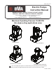
User guide

BEFORE USE
Read, understand, and follow all printed materials carefully
before attempting to assemble or operate these pumps.
NOTICE: E-Pumps are shipped dry. Add oil before use.
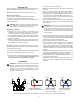
Electrical Connections:
Compare motor nameplate against power availability
to prevent motor burnout and dangerous electrical
overloading. The motors are wired for 110-125 volts unless
otherwise specied.
DANGER: Motor, connections and remote on/off switch
are energized components containing line voltage.
Ensure supply is grounded and GFI protected.
Hydraulic Connections:
1. Make sure to use the hydraulic oil specified by the
manufacturer. Ensure oil level in reservoir is ~ 2" from top
of reservoir plate, with cylinders retracted and motor off.
2. Use of pressure gauge is strongly recommended. Attach a
pressure gauge between the pump and cylinder to monitor
pressure on cylinder.
3. Make sure coupler, hose, valve, gauge are tighten securely
to prevent accidental removal of components while in use.
Hoses must not be kinked or twisted.
NOTICE: Always secure threaded port connections with non-
hardening pipe thread compound. Take care not to introduce
compound into port orices.
To ensure smooth operation, bleed air from the system by fully
advancing and retracting the cylinder several times.
4. Do not exceed the rated capacity of the equipment connected
to the pump. Ensure that all hydraulic equipment used
with this pump is rated at 10,000 psi or greater.
OPERATION
WARNING: ALWAYS monitor pressure, force and load
position. Pressure may be monitored by means of an
optional manifold and gauge. Force may be monitored
by means of a load cell and digital indicator. Correct
application position can only be determined by the
operator of the equipment.
1. Check oil level, add oil if necessary.
2. Make sure system ttings and connections are tight and
leak free.
3. Place control valve lever in the middle (Neutral/Hold)
position to prevent accidental lifting or moving of load.
4. To start the motor: Toggle the ON/OFF switch located on
the control box to 'ON' position OR for momentary use:
Leave control box switch in the 'OFF' position and toggle
remote ON/OFF pendant switch.
5. It is recommended to use to ON/OFF switch at the control
box to let the pump idle for a few minutes before putting
into operation.
WARNING: This pump is for use with a single acting
cylinder ONLY! Connect one hose from either pump
oil output port to the input port of a single acting
application such as a cylinder. Block the unused output
port securely. This model can not be used with double
acting cylinders.
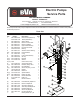
6. Use the control valve lever to control the direction of uid
ow. These pumps are equipped with a 3-way 3-position
valve for use with single acting cylinder applications ONLY.
Refer to Figure 3 below for the ow path.
7. Always monitor the pressure, load and position.
8. Do not exceed the rated capacity of the equipment
connected to the pump. To reduce system component
stress, material fatigue, and the risk of personal injury
and property damage, never load a hydraulic application
(cylinder, spreader, etc.) to more than 80% of its rated
capacity.
9. Shift the control valve until the desired pressure, load or
position is reached. Note: Do not continue to operate pump
after cylinder plunger is fully extended or retracted.
10. To turn off the motor: Toggle the ON/OFF switch on the
control box to 'OFF' position.
11. Depressurize all connections before disconnect. If you
have any questions, call BVA Technical Service @ (888)-
332-6419.
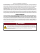
Position 1 (Advance):
Pressured oil ows to port A.
Position 3 (Retract):
Port A returns ow to
tank.
Position 2 (Hold):
Neutral, ports A is
closed. Hold Position.
Port A
Port A
Port A
P T
P T
Figure 3- Schematic ow path, valve position of 3-way, 3-position valve for Single Acting Cylinder
Port A
Port B
1
2
3
5
!
!
!
P T