
Manual
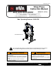


4
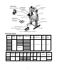
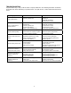
Manual Pumps
Hand
Pump
Model
Usable
Oil
Volume
(in
3
)
Pressure Rating
(psi)
Oil Displacement
(in
3
) Oil Outlet Port
Thread
Weight
(lbs)
1st Stage 2nd Stage 1st Stage 2nd Stage
P1000 61.0
200 10,000 0.81 0.14 3/8”-18 NPTF
13.2
P2001 122.0 24.2
P2301M 128.0 32.3
Air Pumps
Air Pump Model
Usable Oil
Volume
(in
3
)
Pressure Rating
(psi)
Oil Output Flow
Rate (in
3
/min)
Input Air Pressure
Range
(psi)
Weight
(lbs)
No Load Load
PA1500 91.5 10,000 66 11 110 - 175 18.1
Electric Pumps
Electric
Pump
Model
Capacity
(gal)
Pressure Rating
(psi)
Oil Output Flow
Rate (in
3
/min)
Valve
Type
Motor
Size
(hp)
Current
Draw
(A)
Motor
Voltage
(V)
Weight
(lbs)
1st Stage 2nd Stage 1st Stage 2nd Stage
PEM0501T
1 350 10,000 293 18
4-way,
3-pos
0.5 9 115/125 60
PEW0501T
3-way
3-pos
PESL0501T
NOTICE: The power retract feature of the IMPD2506 and IEPD2506 Shop Presses is not intended to be used
under load. Never pull or raise a workpiece with the power retract feature.
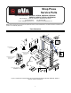
ASSEMBLY
1. Adjust bed frame to lowest position and slacken winch cable.
2. Install the winch assembly to the press using 3 bolts, washers and nuts.
3. Secure cylinder to the cylinder adapter plate, and mount the adapter plate to upper cross member using 4 bolts
and washers.
NOTICE: The cylinder comes with carrying handles, loosen Allen head socket screw to remove the handles.
4. Attach base sections to upright channels with 4 bolts and nuts.
5. Attach lower cross member to upright channels with 4 bolts and nuts.
6. Attach and secure the pump bracket with bolts, nuts & washers provided. (Model IMP2506 & IMPD2506 only)
7. Connect pressure gauge and hydraulic hose to gauge adapter, then connect gauge adapter to pump.
NOTICE: Use thread tape or compound on all connections.
8. For Model IMP2506, IMP2514 & IMPD2506: Place pump on pump bracket and connect hydraulic hose end to
cylinder.
CAUTION: Before disassembly, slide bed frame section down to lowest position.
OPERATION
Before Use
1. Inspect before each use. Do not use if bent, broken or cracked components are noted. Check for and tighten any
loose assemblies. Replace worn or damaged parts and assemblies with BVA authorized replacement parts only.
2. Verify that the product and the application are compatible, if in doubt contact BVA Technical Service (816) 891-6390.
3. Before using this product, read this operator’s manual completely and familiarize yourself thoroughly with the
product, its components. Recognize the potential hazards associated with its use.
!