
Operating instructions


(1)
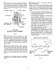
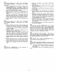
INSTALL CAST IRON CLEANOUT COVERS to
the boiler with
x"
x
2%''
long bolts provided. The bolts
should be anchored to the slots in the cleanout openings
of the sections with
the head of the bolt and
a
washer
inside and a washer and nut outside. See Figure 5. The
covers are placed on the bolts.and secured with washers
and nuts.
CLEANOUT COVER
7
r
COVER GASKET
INSULATION
CLEANOUT NUT
AND WASHER
WASHERS
TOP
VIEW
CLEANOUT COVER ASSEMBLY
Fig.
5
'
@
FLUE COLLAR should be assembled next. Clean
the ground surface on the flue collar and the mating
ground surface on the back section with
a
wire brush.
Then using a cartridge of silastic sealant provided, apply
a smooth
1/4"
diameter bead of sealant to the ground sur-
face on the back section. Place the collar on the back
section and position the damper bracket on the collar as,
shown in Figure
1.
Secure the collar with the 5/16"
bolts provided.
@
INSTALL BURNER PLATE as follows: Clean the
ground surface on the burner plate and the mating sur-
face on the front section with a wire brush. Then using
a cartridge of sealant provided, apply a smooth
s"
diam-
eter bead of sealant to the ground surface of the front
section. Secure the burner plate to the front section with
the 5/16 x
1"
long bolts provided. Draw-up the bolts
until the burner plate makes contact with the front
section.
IMPORTANT-THIS BOILER DOES NOT REQUIRE
A COMBUSTION CHAMBER OR SEPARATE SMOKE-
HOOD.
@)
CONNECT SUPPLY AND RETURN PIPING TO
HEATING SYSTEM.
NOTE-If jacket extension (special order only) is to be
installed now or in the future, return piping connected
to front section must pass thru opening provided in ex-
tension, see Fig.
1.
In addition, fittings used to connect
circulator in this return (water boiler) must be selected
so that circulator does not extend beyond sides of flush
jacket.
a. If boiler is equipped with tankless heater, hot and
cold water lines must be routed thru opening pro-
vided in Jacket Extension Top Panel. Refer to FIG.
18 for
Tankless Heater Piping.
b. All Piping must be installed so as to provide clear-
ance for running the Smokepipe as direct as possible
between the Boiler and Chimney.
c. With Forced Circulation HOT WATER HEATING,
consult I-B-R Installation and Piping Guide No.
200.
NOTE: When Hot Water Heating Boilers are con-
nected to Heating Coils located in Air Handling
Units where they may be exposed to refrigerated
air circulation, the Boiler Piping System must be
equipped with Flow Control Valve or other auto-
matic means to prevent gravity circulation of the
Boiler Water during Cooling Cycle.
d. With STEAM HEATING, see Figures
7
and 8.
Consult I-B-R Piping Guide No.
200.
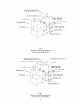
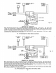
e. With COMBINATION HEATING AND COOLING
(REFRIGERATION) SYSTEMS having the same
Distributing Units, Piping and Circulator, see Fig-
ure 6. NOTE: Valves must be installed in each
Supply and Return Branch to the Heating Boiler
and Water Chiller so as to prevent circulation of
Chilled Water through the Boiler or Heated Water
through the Chiller.
Hm
ARE CLOSED IN WINTER AND OPEN IN SUMMER
ARE OPEN IN WINTER AND CLOSED IN SUMMER
WATER
CHILLER
--Ic
n
I
SHUT- OFF
r
SHUT- OFF
I
VALVE
HEATING
A
d
BOILER
I
[AIR CUSHION TANK
I
SUPPLY MAIN
If"
RETURN MAIN
TO COMBINED
CIRCULATOR FROM
COMBlNECl
HEATING
8
HFATING
I3
COOLING
SYSTEM
'1
,
,
.;;;;;
M-
-
COOLING
RECOMMENDED PIPING FOR COMBINATION
HEATING
8
COOLING IREFRIGERATION) SYSTEMS
Fig.
6