
Operating instructions


SECTION I1
INSTALLATION
INSTRUCTIONS
a
Place boiler assembly on foundation provided. Shim
if necessary. The tie rod nuts should then be loosened
until finger tight.
"INSTALLATION OF BUILT-IN HEATERS AND
HEATER OPENING COVER PLATES"
@
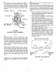
INSTALLATION OF BUILT-IN DOMESTIC WA-
TER HEATER if furnished.
a. Slip Rubber Gasket over Heater Coil and place
against Heater Mounting Plate so that holes in
Gasket are in line with holes in Heater Mounting
Plate.
b. Install Built-in Heater Coil through
openihg in
Front Section into the upper nipple port for water
boilers or the lower nipple port for steam boilers.
(See Fig.
4).
c. Secure the Heater Mounting Plate with
3/8
Hex
Head Cap Screws and Flat Washers (if furnished).
Snug all screws before final tightening.
d. Attach the Tapped Heater Cover Plate with Rubber
Gasket to the remaining opening in the Front Sec-
tion. Secure with
3/8"
Hex Hd. Cap Screws and
Flat Washers (if furnished). Snug all screws before
tightening.
@
INSTALLMENT OF HEATER OPENING COVER
PLATES if Built-in Domestic Water Heater is not fur-
nished. (Steam and Water Boilers). See Figure
l.
a. Attach Blank Heater Cover Plate with Rubber Gas-
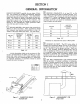
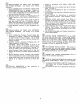
LlMlT CONTROL OR COMBINATION
Iml
HlGH LlMlT AND CIRCULATOR
CONTROL (FOR INSTALLATIONS
WITHOUT
TANKLESS
WATER
HEATER)
LOCATION
ON BOILER
A
COMBINATION HlGH LIMIT, LOW LlMlT
AND CIRCULATOR CONTROL (FOR
INSTALLATIONS WITH TANKLESS
1 1
HEATER)
SIZE
(INCHES)
1
AUXILIARY LlMlT CONTROL (WHEN
I
NEEDED-TEQUIRES ADDITIONAL
TAPPED HEATER OPENING COVER
P~OUT
TANKLESS HEATER)
WATER
'ONTRoL
SAFETY RELIEF USED
D
F
(11/2
1
NOT USED
COMBINATION PRESSURE AND
TEMPERATURE GAUGE
BUSH TO 1/4"
-
PRESSURETROL-
OR OPTIONAL CONTROLS
G
H
STEAM PRESSURE GAUGE
d
GAUGE GLASS AND LOW WATER
CUT-OFF
1/2
3/4
ket to the lower nipple port in Front Section using
3/8"
Hex Hd. Cap Screws and Flat Washers (if
furnished). Snug all screws before final tightening.
b. Attach the Tapped Heater Cover Plate with Rubber
Gasket to the upper nipple port in Front Section
using
3/8"
Hex Hd. Cap Screws and Flat Washers
(if furnished). Snug all screws before final tight-
ing.
NOT USED
AUXILIARY TAPPING
@
TEST BOILER FOR LEAKS before installing con-
trols, trim, and jacket, and before connecting to heating
system.
a. Install Pressure Gauge (at least
30
P.S.I. capacity),
a hose to the City Water and a valve in one of the
supply tappings. Plug remainder of tappings.
b. Fill Boiler with water and apply a pressure of at
least
10
pounds but no more than
50
pounds gauge
pressure.
c. Examine Boiler carefully inside and outside for leaks
or damage due to shipment or handling.
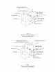
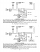
DRAIN WATER FROM BOILER. Remove gauge,
valve and plugs from those tappings to be used.
Leave
other tappings plugged or bushed according to Figure
4.
@
INSPECT JOINTS BETWEEN SECTIONS. All
joints are factory sealed. If there are any spaces due to
shipment or handling, seal them with silastic sealant.
WATER HEATER A
,3'
SUPPLY
(OPTIONAL)=
IN BACK SECTION
1nw
OR9UI
VUkE
rnw~Amws~w
STEAM BOILER
WATER BOILER
-
-
AUXILIARY TAPPING-BELOW
NORMAL WATER LINE
I
Fig.
4
4