
Operating instructions


SECTION I
GENERAL
INFORMATION
INSPECT SHIPMENT carefully for any signs of dam-
@
PROVIDE CLEARANCE of at least
24"
on the
age. All equipment is carefully masufactured, inspected
right side and back of the unit for cleaning of flues. Pro-
and packed by experienced workmen. Our responsibility
vide a minimum of
20"
clearance in front for servicing of
ceases upon delivery of boiler to the carrier in good con-
equipment,
30"
if boiler is equipped with jacket extension.
dition. Any claims for damage in shipment must be filed If boiler is equipped with tanldess heater, additional
immediately against the carrier by the consignee.
No
allowance may have to be made for installation and serv-
claims for variances from, or shortage in orders, will be icing of heater, see table below:
allowed by the manufacturer, unless presented within
sixty
(60)
days after receipt of goods.
a
LOCATE BOILER so that smoke pipe connection
to
chimney is short and direct. Floor construction should
have adequate load bearing characteristics to bear the
weight of the boiler filled with water. See table below.
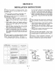
HEATER
N
0.
226
232
445
HEATER
CLEARANCE
INCHES
2 3
29
35
TOTAL
WEIGHT
BOILER
N
0.
Table "B"
Distances are measured from front of flush jacket.
@
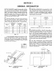
CHIMNEY OR VENT. The PF-3 series boiler is
designed for forced-draft firing and may be used with a
conventional natural draft stack or a stub vent (see Fig-
ure
3).
See Fig.
1
for the proper vent size.
Draft con-
trols are not normally required, although they may be
Table "A"
used on installations where a natural draft stack is used
or on multiple boiler installations with a common stack.
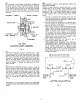
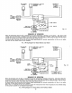
A boiler foundation similar to the one shown in Fig-
The boiler is provided with
a
breeching damper which
ure
2
is recommended if the boiler room floor is not Per-
should be secured in the open position unless high breech-
fectly level, weak, uneven or if a water condition exists.
ing draft makes burner adjustment difficult.
If the boiler is set on a combustible floor, a
1"
thick layer
of foil-faced insulation or equivalent should be placed
beneath the boiler foil side up.
@
AIR FOR COMBUSTION AND VENTILATION
must be provided. If natural ventilation is inadequate,
provide a screened opening from the boiler room to the
outside, which is based on one square inch free
afea per
rl
3000
btuh input. If other air consuming appliances are
near the boiler the air inlet should be larger. Consult
respective manufacturers.
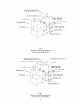
44.
50.
114
X
4
STEEL
PLATE
/
Figure
2
-
SUGGESTED BOILER Figure
3
-
ARRANGEMENT FOR
FOUNDATION STUB VENT
3
(LBS.)
1076
1335
1602
1865
P
F-34
P
F-35
P
F-36
P
F-37
ASSEMBLED
SECTION
WEIGHT
WATER
CONTENT
FULL
(LBS.)
800
1000
1200
1400
(LBS.)
276
335
402
465