
Operating instructions


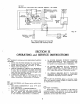

ATTENTION TO BOILER WHILE IN OPER-
ATION.
a. On steam boilers at the start of each heating season
and once or twice during the season try SAFETY
VALVE to be sure it is in working condition. A
try lever test should be performed as follows: with
the boiler under a minimum of 5 psi pressure, lift
the try lever on the safety valve to the wide open
position and allow steam to be discharged for 5 to
10
sec. release the try lever and allow the spring
to snap the disk to the closed position. If valve
leaks operate lever two or three times to seat disk
properly. If valve continues to simmer it must be
replaced or repaired. It is advisable to have a
chain or wire attached to lever of valve so test can
be conducted in a safe manner.
b. On a water system at the start of each heating sea-
son and once or twice during the season try safety
relief valve to be sure it is in working condition.
A try lever test should be performed as follows:
1) Lift the try lever to the open position and hold
it open for at least 5
sec or until clear water is discharg-
ed.
2) Release the lever and allow the spring to snap the
disk to the closed position.
If the valve leaks, operate
the try lever two or three
times to clear the seat of any
object that is preventing proper seating. As safety re-
lief valves are normally piped to the floor or near a floor
drain. it may take some time to determine if the valve
has shut completely.
3) If the safety relief valve continues to leak it shall
be replaced with
a
new valve, returned to the manufac-
turer for repair or field repaired by the manufacturer.
ATTENTION TO BOILER WHILE NOT IN
OPERATION.
-
The boiler and steam system should be
inspected
at
least once each year by a competent .service-
man to insure continued reliable, safe operation.
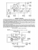
Clean Boiler as follows at the end of each heating
season.
a. Remove upper right hand jacket panel by remov-
ing screws, lifting and swinging out bottom of panel
using two finger holes.
b. Access to boiler flue ways may be gained by remov-
ing nuts and washers securing cast iron
cleanout
covers. Refer to Figure 5..
c. Thoroughly clean flue ways using a flue brush.
d.
Remove and clean smokepipe where feasible.
e. Replace smokepipe and cleanout covers.
f. Replace upper right hand jacket panel.
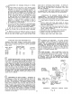
TANKLESS HEATER PERFORMANCE
Tankless
water heater ratings for PF-3 boilers (steam
and water) are given in gallons per minute continuous
draw of water heated from 40°F to 140°F with 200°F
boiler water.
Tankless Water
(
Boiler Model Heater Number Pressure
Number 226 232 445 Drop (psi)
PF-34 6.0
23
PF-35 6.0 7.5
36
PF-36
6.0 7.5 9.0 37
PF-37
,
6.0 7.5 9.0 37
a
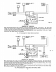
FLOW REGULATION-If flow through the heat-
er is greater than its rating, the supply of adequate hot
water may not be able to keep up with the demand. For
this reason a FLOW REGULATOR matching the heater
rating should be installed in the cold water line to the
heater. The flow regulator should preferably be located
below the inlet to the heater and
a
minimum of 3' away
from the inlet so that the regulator is not subjected to
excess temperatures that may occur during "off" periods
when it is possible for heat to be conducted back through
the supply line. The flow regulator also limits the flow
of supply water regardless of inlet press variations in the
range of 20 to 125 psi.
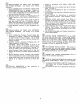
TEMPERING OF HOT WATER
-
Installation of
a tempering or mixing valve will lengthen the delivery of
the available hot water by mixing some cold water with
the hot. This prevents excessive and possibly scalding
hot water at the fixtures. In addition, savings of hot
water will be achieved since the user will not waste as
much hot water while seeking water temperatures to his
liking. Higher temperature hot water required by dish-
washers and automatic washers is possible by piping the
hot water from the heater prior to entering the mixing
valve. The mixing valve should be "trapped" by install-
ing it below the cold water inlet to heater to prevent lime
formation in the valve.
@
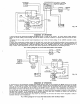
FLUSHING OF HEATER
-
All water contains
some sediment which settles on the inside of the coil.
Consequently, the heater should be periodically back-
washed. This is accomplished by installing hose bibs as
illustrated and allowing water at city pressure to run
into hodebib A, through the heater, and out hosebib B
until the discharge is clear. The tees in which the hose
bibs are located should be the same size as heater con-
nections to minimize pressure drop.
-
(?)
HARD WATER
-
This is applicable to some city
water and particularly to well water. This should not
be a deterent but precautions are necessary. A water
analysis
is necessary and an appropriate water softe-
ncr installed.
This is not only beneficial to the heater
but to piping and fixtures plus the many other benefits
derived from soft water.
SAFETY
RELIEF
VALVE
TANKLESS
HEATER
7
TEMPERED
HIGH TEMP.
WATER FOR
HOT WATER AUTOMATIC
TO FAUCETS
AND SHOWERS
COLD
GLOBE VALVE
WATE~
OR
SQ.
HD. COCK
SUPPLY
;
IN COLD WATER
LINE AT LEAST
3
FEET
AHEAD OF TANKLESS
HEATER
SCHEMATIC
15
TANKLESS HEATER PIPING
Fig.
18