
Operating instructions


7
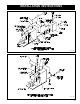
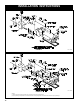
1. BOILER PIPING
Attach supply and return piping lines and insert plugs
and bushings in connections as required. Supply and
return piping headers are detailed in Figure 2.
IT IS IMPORTANT TO COMPLY WITH THE MINIMUM
PIPING REQUIREMENTS IN ORDER TO ENSURE
MAXIMUM PERFORMANCE AND RELIABILITY. ON
STEAM BOILERS, PARTICULAR ATTENTION SHOULD
BE GIVEN TO THE CONSTRUCTION OF THE SUPPLY
HEADER.
The nominal temperature differential between supply
and return water recommended for Burnham retube
water boilers is 20°F. As a precaution against thermal
shock, this differential should never exceed 40°F.
When differentials in excess of 30°F are anticipated
on rebox boilers, the return water should enter the boiler
at the top tting (normally the supply) and the supply
water should leave the boiler through the bottom tting
(normally the return). This ow pattern directs the return
water over the relatively cool third pass rather than
directly against the rear of the furnace.
The boiler should not be operated for any length of
time at a temperature setting that allows the formation of
condensation in the tubes or smokebox. This generally
dictates a minimum setting of approximately 140°F on
the low limit on systems with a 20°F system differential.
On cold start up, condensation can be expected until the
boiler warms up. If formation of condensate persists, the
low limit should be adjusted upward until condensate no
longer forms.
Water boilers and low pressure steam boilers must
have a set LFH at 120° minimum to avoid condensation.
High pressure steam should have a minimum LFH
temperature of 180°F.
2. RECOMMENDED WATER BOILER
RECIRCULATION LOOP
The following guidelines relating to system water
temperature uctuation and ow through the boiler must
be observed.
A. It is important to operate your boiler in such a
manner as to prevent temperature uctuation of
more then 40°F at any time. Rapid temperature
changes within the boiler can create stresses in the
boiler metal. These stresses can cause damage to
the boiler by loosening tubes, or in more severe
instances can crack tube sheet ligaments,
furnaces, or waterlegs.
B. If temperature differentials approach 40°F, to
help prevent temperature uctuations and insure
proper circulation through the boiler, a recirculation
loop as shown in Figure 10 should be considered.
The recirculation ow should be at least 1/2 GPM/
BHP at all times when the boiler is online
for operation.
3. TANKLESS HEATER
A. If boiler is ordered with tankless heater, connect
tankless heater piping as shown in Figure 2.
Install an automatic mixing valve at the tankless
heater outlet to avoid risk of burns or scalding due to
excessively hot water at the xtures. Adjust and maintain
the mixing valve in accordance with the manufacturer’s
instructions.
B. The following guidelines should be followed when
piping the tankless heaters:
4. FLOW REGULATION
If ow through the heater is greater than its rating, the
supply of adequate hot water may not be able to keep
up with the demand. For this reason a ow regulator
matching the heater rating should be installed in the
cold water line to the heater. The ow regulator should
preferably be located below the inlet so it's not subjected
to excess temperatures that may occur during “off”
periods when it is possible for the heat to be conducted
back through the supply line. The ow regulator also
limits the ow of supply water regardless of inlet
pressure variations in the range of 20 to 120 psi.
5. TEMPERING OF HOT WATER
Installation of an automatic mixing valve will lengthen
the delivery of the available hot water by mixing some
cold water with the hot. This prevents excessive and
possibly scalding hot water. Higher temperature hot
water is possible by piping the hot water from the heater
prior to entering the mixing valve. The mixing valve
should be “trapped” by installing it below the cold water
inlet to heater to prevent lime formation in the valve.
SECTION II — INSTALLATION INSTRUCTIONS
FIGURE 2
SCHEMATIC TANKLESS HEATER PIPING
CAUTION
WARNING
WARNING