
MegaSteam Installation, Operating, and Service Instructions


66
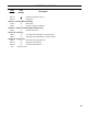
Boiler
Model
Burner
Input
(GPH)
Burner
Model
Nozzle
Head
Setting
Air
Setting
Pump
Pressure
(PSI)
Air Tube
Type
Insertion
Depth
(Inch)
Approx.
Shipped
CO
2
(%)
Bafe
Location
(pass)
Approx.
Stack Temp.
Increase
Without
Bafes °F
(2)
Approx.
Breech
Pressure
(" w.c.)
(3)
Bafes IN
Approx.
Overre
Pressure
(" w.c.)
(3)
Bafes OUT
Approx.
Overre
Pressure
(" w.c.)
(3)
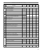
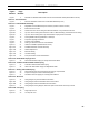
MST396 1.05 EZ-66
0.85 x 45AS
Danfoss
2.0 40 150
Conical
Wrap
2-5/8 11.5 2
nd
65 0 +0.040 +0.020
MST513 1.35 EZ-66
1.10 x 45B
Delavan
3.5 50 150
Conical
Wrap
2-5/8 11.5 2
nd
39 0 +0.040 +0.030
MST629 1.65 EZ-66
1.35 x 45B
Hago
5.5 60 150
Conical
Wrap
2-5/8 11.5 2
nd
18 0 +0.050 +0.030
Notes
(2)
The increased stack temperature with the bafes removed is an approximation, based on a constant supply temperature of 180°F and 11.5% CO
2
. Actual eld conditions may be different.
(3)
These values are minimum and could be as much as -.03" w.c., more without impacting performance. Pressures based on 11.5% CO
2
. Example: MST629 could have a breech pressure of
-.03" w.c. and an overre pressure of .020" w.c.
4) Single stage fuel pump is standard, two-stage fuel pump is optional. Burner manufacturer has preset single stage fuel pump to settings shown in table above. Two-stage fuel pump is factory
set at 140 PSI and must be readjusted to settings shown
above during burner start-up.
TABLE 7B: CARLIN BURNER SPECIFICATIONS
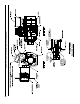
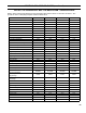
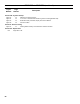
SECTION XII: REPAIR PARTS (continued)