
Installation and Operation Manual

69
f. Use a wire or ber bristle brush of appropriate
length and diameter to allow sufcient cleaning
of all ue passages. Using long strokes, push the
brush the whole way through the boiler and then
pull it out. Repeat this process until all surfaces
of each of the ue passages have been cleared of
all soot and debris.
g. Vacuum all loose debris that has collected in
the rear of the combustion chamber and in the
turnaround passages into the second ue passes.
h. Use a wire or ber bristle brush to clean all of
the surfaces of the combustion chamber and
turnaround passages to the second ue passes.
i. Vacuum all loose debris in the bottom of the
combustion chamber and in the turnaround
passages to the second ue passes.
j. Remove the ue collector clean-out covers at
the rear of the boiler by removing four (4) 5/16”
cap screws and washers. Through these clean-
out openings, vacuum all loose debris from the
bottom of the ue collector.
3. REASSEMBLE BOILER.
a. Reattach the ue collector clean-out covers to
the rear of the boiler, verifying that the silicone-
coated rope gaskets are still in satisfactory
condition. Replace the rope gaskets, if
necessary, before reassembly. Tighten the covers
snugly into place using original 5/16” hardware.
Do not over tighten.
b. Insert the ue bafes into the appropriate ue
passes.
c. Inspect the insulation and silicone-coated rope
gasket on the inside of the BSD, making sure
that everything is in place and undamaged. If
the BSD insulation or rope gasket is damaged,
replace them.
d. Carefully close the BSD and secure it in place
using the original 9/16” hardware. When
tightening the bolts, make sure that the BSD
is drawn in equally at all four corners. Use an
alternating tightening method from corner to
corner to pull the door tight equally around the
perimeter.
Do not overtighten. The rope gasket will provide
sufcient seal when the door is snugged in
place.
e. Reinstall the burner to the BSD (if removed) and
secure it in place on its support pedestal. Inspect
the burner gasket to assure an adequate seal.
Replace it if damaged.
f. Connect the fuel lines.
g. Reattach the BSD cover panels (if provided).
Do not start the burner unless BSD, smokepipe,
ue clean-out covers and burner are all secured
in place.
C. MAINTENANCE OF LOW WATER CUTOFF
DEVICES
Probe and oat type low water cutoff devices
require annual inspection and maintenance.
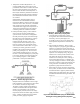
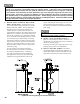
1. PROBE TYPE LOW WATER CUTOFF
Although these devices are solid state in their
operation, the probe is exposed to possible
contamination in the boiler water and subject to
fouling. It is important to physically remove the
probe from the boiler tapping annually and inspect
that probe for accumulation of scale or sediment.
Follow these steps to inspect, clean and /or replace
the probe:
a. Turn off electric service to the boiler.
b. Close isolation valves in supply and return near
boiler piping.
c. Drain boiler water to a level below the tapping
for the probe.
d. Disconnect wiring connections between the low
water cutoff control and the probe.
Assure that the boiler is at zero pressure before
removing the LWCO probe. Do not rely on the
pressure gauge to indicate that the boiler is at
zero pressure. Open the relief valve to relieve
all internal pressure prior to proceeding. Relief
valve discharge piping must be piped such that
the potential for burns is eliminated.
e. Dismount the low water cutoff control from the
probe.
f. Unscrew the probe from the boiler tapping.
g. Inspect that portion of the probe that is exposed
to the boiler water for a scale or sediment
buildup.
h. Light deposits may be removed by wiping the
probe with a damp cloth. Wiping the probe
with a cloth soaked in vinegar will remove more
tenacious lime deposits. The most stubborn
deposits may be removed from the probe by
using a diluted amount (3 part of water to 1 part)
of phosphoric acid (H
2
PO
4
).