
Installation and Operation Manual

58
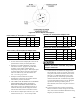
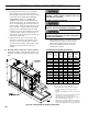
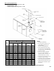
* Width can vary with gas train conguration.
** Varies slightly with burner and gas train conguration.
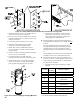
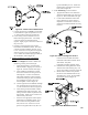
1. Do not tilt. Exercise caution when lifting to avoid
damage.
2. This boiler can be lifted by fork truck. Do not truck from
front.
3. When lifting from rear, forks must extend from beyond
center of gravity and second skid cross bar.
4. When lifting from side, forks must extend to opposite
skid rail and straddle center of gravity.
5. Cablespreader is to prevent jacket damage. Spreader
width should equal B (width of skid) + 12”. Adjust cable
lengths to lift at approximate center of gravity per chart.
SECTION IV - INSTALLATION INSTRUCTIONS
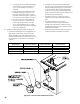
Packaged Boiler Shipping Information
Figure 48: Packaged Boiler Shipping Information
A. PACKAGED BOILER
1. The packaged boiler comes on its own shipping
skid (see Figure 48) and the assembled block is
hydrostatically tested at the factory. Once the boiler
is in its nal position, PERFORM ANOTHER
HYDROSTATIC TEST AT 1½ TIMES THE
WORKING PRESSURE OF THE BOILER (see
Section II, Paragraph C). The shipping skid can be
used as a housekeeping pad unless local codes say
otherwise. Most controls are pre-wired down to the
burner. If burner is equipped with a lead lag panel,
lead lag controls will be shipped loose for header
mounting. The power can be supplied to the burner
if equipped with a control panel. If burner has no
panel, the power must be supplied to a junction box
near the front of the boiler.
2. If the boiler burner unit was factory re tested,
the burner was adjusted to approximately 10.2%
CO2 (gas) or 13.2% CO2 (oil) with an overre
pressure as listed in Table II of this manual. Final
adjustments should be made once the unit is
installed.
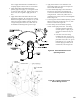
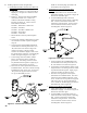
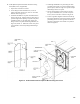
B. BOILER PIPING - HEATING APPLICATIONS
CONNECT SUPPLY AND RETURN PIPING TO
HEATING SYSTEM (see Figures 49a, 49b, 50a and
50b).
Failure to properly pipe boiler may result in
improper, unsafe system operation and void
manufacturer’s warranty.
DO NOT improperly pipe boiler.
All hot water pipes must have clearances of at
least 1/2” from all combustible construction.
A hot water boiler installed above radiation level
must be provided with a low water cutoff device
as part of the installation.
1. HOT WATER HEATING - This boiler must be
installed in strict accordance to the instructions
found in this installation manual. Deviations
from these installation instructions may void
manufacturer’s warranty.
Number of
Sections
Length
A
(Inch)
Width
B *
(Inch)
Height
C
(Inch)
Approx.
Center of
Gravity D
** (Inch)
Approx.
Shipping
Weight
(Lbs.)
4 77½ 48 61½ 23¼ 2789
5 83½ 48 61½ 26¼ 3272
6 95½ 48 61½ 29¼ 3755
7 101¾ 48 61½ 32½ 4249
8 108 48 61½ 35½ 4783
9 114 48 61½ 38½ 5261
10 130¼ 48 61½ 44½ 5757
11 136½ 48 61½ 47¾ 6236
12 142½ 48 61½ 50¾ 6739
13 148½ 48½ 61½ 53¾ 7227
14 154¾ 48½ 63½ 57 7760
15 161 48½ 63½ 60 8335
16 167 48½ 63½ 63 8824
17 173 48½ 63½ 66 9324
18 179¼ 48½ 63½ 69¼ 9823