IN S TAL L AT ION , OP E R AT IN G AN D S E R V IC E IN S T R U C T ION S F OR M o d e l M P C ™ M U LT I - P A S S C O M M E R C I A L C A S T I R ON BOI L E R 3050579 This manual must only be used by a qualified heating installer/service technician. BEFORE installing, read all instructions in this manual and all other information shipped with the boiler. Post all instructions and manuals near the boiler for reference by service personnel. Perform steps in the order given.
IMPORTANT INFORMATION READ and save these instructions for reference All boilers must be installed in accordance with National, State and Local Plumbing, Heating and Electrical Codes and the regulations of the serving utilities. These Codes and Regulations may differ from this instruction manual. Authorities having jurisdiction should be consulted before installations are made. In all cases, reference should be made to the following Standards: USA BOILERS A.
This boiler has a limited warranty, a copy of which is printed on the back of this manual. It is the responsibility of the installing contractor to see that all controls are correctly installed and are operating properly when the installation is complete. The warranty for this boiler is valid only if the boiler has been installed, maintained and operated in accordance with these instructions. DO NOT store or use gasoline or other flammable vapors or liquids in the vicinity of this or any other appliance.
Appliance materials of construction, products of combustion and the fuel contain alumina, silica, heavy metals, carbon monoxide, nitrogen oxides, aldehydes and/or other toxic or harmful substances which can cause death or serious injury and which are known to the state of California to cause cancer, birth defects and other reproductive harm. Always use proper safety clothing, respirators and equipment when servicing or working nearby the appliance. This boiler contains very hot water under high pressure.
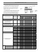
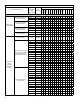
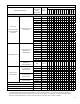
EQUIPMENT CHECK LIST NOTE: Only factory packaged and firetested units are eligible to bear the UL listing mark. This Equipment Check List has been provided so that the Installer can determine if all parts have been provided for the boiler ordered. It covers standard equipment for Knockdown boilers, 4 thru 18 section models. Optional equipment ordered will be in addition to, or in lieu of, equipment shown below.
KNOCKDOWN BOILER - EQUIPMENT CHECK LIST 1 1 18 Sect. 1 17 Sect. 1 16 Sect. 1 15 Sect. 14 Sect. 1 13 Sect. 1 12 Sect. 1 11 Sect. 9 Sect. 1 10 Sect. 8 Sect. 7 Sect. 6 Sect. 5 Sect. Part Number 4 Sect. Component Description Carton Designation on Bar Code Label (Continued) Qty. Req’d.
KNOCKDOWN BOILER - EQUIPMENT CHECK LIST 18 Sect. 17 Sect. 16 Sect. 15 Sect. 14 Sect. 13 Sect. 12 Sect. 11 Sect. 10 Sect. 9 Sect. 8 Sect. 7 Sect. 6 Sect. 5 Sect. Qty. Req’d. Per Boiler Size Part Number 4 Sect.
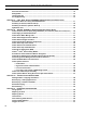
Table of Contents SECTION I - GENERAL INFORMATION Dimensional Information.................................................................................................................. 10 Ratings/Data........................................................................................................................................ 12 Locating the Unit ...............................................................................................................................
Table of Contents (continued) SECTION VI - SERVICE INSTRUCTIONS Cleaning Boiler Heating Surfaces..................................................................................................... 68 Maintenance of Low Water Cutoff Devices...................................................................................... 69 Checking Burner & Controls............................................................................................................. 70 Lubrication.........................
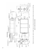
Figure 1b: Dimensional Information * Wiring harness shown in this location for illustration purposes - typically, wiring harness leads will exit jacket on same side as BSD hinges.
14 15 16 17 18 MPC15 MPC16 MPC17 MPC18 128-3/8 121-5/8 114-7/8 108-1/8 101-3/8 94-5/8 87-7/8 54 47-1/4 40-1/2 33-3/4 26-3/8 26-3/8 26-3/8 22-1/2 22-1/2 22-1/2 22-1/2 22-1/2 21 21 21 20-1/2 20-1/2 12-1/4 10-1/4 CF 29-3/8 29-3/8 29-3/8 29-3/8 29-3/8 29-3/8 29-3/8 29 29 29 29 28-1/2 28-1/2 21-3/4 20-3/4 CG Beckett 39-1/2 39-1/2 39-1/2 39-1/2 34-5/8 34-5/8 34-5/8 34-5/8 34-5/8 34-5/8 34-5/8 29-5/8 29-5/8 29-5/8 29-5/8 C --- --- --- ---
TABLE II: Ratings/Data Model MPC™ Boilers (2) (3) (4) Gas (MBH) Gross Output (MBH) Net I=B=R Rating (MBH) Oil - % Gas - % Heating Surface (Sq. Ft.) Net Furnace Volume (Cu. Ft.) Pressure in Firebox (Inches Wtr. Column) Water Content (Gallons) 3.5 485 500 424 368 87.3 84.7 75.0 7.1 0.10 63 2820 7 MPC5 19.5 5.4 750 773 652 567 86.9 84.3 95.3 9.1 0.19 78 3396 7 MPC6 25.0 6.9 964 995 837 728 86.8 84.1 115.5 11.0 0.28 93 3972 8 MPC7 30.5 8.
SECTION I - GENERAL INFORMATION (Continued) A. INSPECT SHIPMENT carefully for any signs of • damage. 1. ALL EQUIPMENT is carefully manufactured, inspected and packed. Our responsibility ceases upon delivery of crated Boiler to the carrier in good condition. • • 2. ANY CLAIMS for damage or shortage in shipment must be filed immediately against the carrier by the consignee.
Table V: Minimum Installation Clearances To Combustible Materials (Inches) per UL726 (Packaged / Firetested Boiler) This boiler is NOT suitable for installation on combustible floor. Floor construction should have adequate load bearing characteristics to bear the weight of the boiler filled with water (see Table 1). A boiler foundation similar to the one shown in Figure 2 is recommended if the boiler room floor is weak or uneven or if a water condition exists. 4.
a. In the absence of local requirements, the confined space shall be provided with two permanent openings, one in or near the top of the room and one near the bottom. The openings shall communicate by means of ducts, with the outdoors or to such spaces (crawl or attic) that communicate with the outdoors. i. Where communicating by means of vertical ducts, each opening shall have a free area of not less than 1 sq. in. per 4,000 Btuh (35 sq. in. per gph.) (5.
Single wall Type C vent material is not approved for MPC boiler venting. When an MPC gas fired boiler is connected to a venting system that is designed so that it will operate under a positive pressure, manufactured vent systems, designed and approved for positive pressure application per UL1738, must be used (for example, Van-Packer Model CS, Protech Model FasNSeal / FasNSeal W2, Heatfab Saf-T-Vent or equivalent).
SECTION II - CAST IRON BLOCK ASSEMBLY INSTRUCTIONS (Knockdown Boilers) NOTE: Only factory packaged and firetested units are eligible to bear the UL listing mark. outlined in Section I. Lifting arrangement and weights A. FACTORY ASSEMBLED SECTIONS - The assemblage should be set in the proper location as are given in Figures 4a and 4b.
Then proceed to Step C of this section on Page 24, “HYDROSTATIC TEST”. B. FIELD ASSEMBLED SECTIONS - If the boiler was ordered knockdown, to be field assembled, follow the assembly procedure outlined on the following pages. 1. ASSEMBLY OF SECTIONS (MANUAL DRAWUP) These sections are designed to be drawn together one section at a time using the Manual Draw-up Kit (Burnham P/N 102008-01 or P/N 102008-02) using ordinary hand tools.
Figure 5: Manual or Hydraulic Draw-up Section Assembly
Figure 6: Vertical Bracing of Rear Section Figure 7: Setting of Nipples 20 Figure 8: Inspection Pad Locations for Section Draw-up
This is a forced draft fired boiler and sealant must be applied where specified for proper and safe performance. Burnham Commercial has approved section joint sealants (silastics) manufactured by Dow-Corning under the product number RTV 736, and Sil-Bond under the product number RTV 6500. Sections must be drawn-up tight immediately after properly applying sealant for best results. Although sections may be joined within two (2) hours of applying sealant, humidity and temperature affect cure time.
adjacent sections as the boiler operates with a positive pressure in the firebox and products of combustion will escape between sections unless they are properly sealed. The rope and sealant should be applied before each section is placed on the assembly. All casting legs have two (2) holes. Slide the lower retention rods through the upper hole in each leg. Start at the front or rear, which ever is easiest, per the arrangement shown in Table VI.
the opposite end of threaded rod in upper nipple port. Place remaining 6½” dia. pressure plate on rod protruding through lower nipple port. 2. ASSEMBLY OF SECTIONS (HYDRAULIC DRAW-UP) • MPC4 through MPC12 Section Assemblies The entire assemblage may be drawn-up at one time using the hydraulic draw-up equipment providing the operation is completed within two (2) hours after the sealant was applied to the first casting in the assembly.
Step f. After all sections have been drawn up, retention rods must be installed. Do not release hydraulic pressure until the retention rods are in place. Step g. Locate the threaded 5/8” retention rods, washers, tension springs and nuts supplied in ‘BAC’ Boiler Assembly Carton. Assemble both top retention rod assemblies as shown in Figure 5, Detail B, using the proper arrangement per Table VI. The tension spring should always be located at the rear of the boiler.
Figure 9: Installation of Common Parts to Block Assembly SECTION III - BOILER ASSEMBLY INSTRUCTIONS (Knockdown Boiler)
SECTION III - BOILER ASSEMBLY INSTRUCTIONS (KD Boiler) - Continued NOTE: Only factory packaged and firetested units are eligible to bear the UL listing mark. A. INSTALL COMMON PARTS TO BLOCK ASSEMBLY, Refer to Figure 9. 1. Remove contents from Common Parts Carton marked ‘CPC’. 2. Locate four (4) C. I. burner swing door (BSD) hinge/latch castings, two (2) C. I. BSD hinge loop castings, ten (10) 7/16 split lock washers and ten (10) 7/16 -14 x 1-1/2 lg. cap screws.
f. Install observation port sight glass. Locate 2” x 2-1/2” lg. nipple, sight glass envelope and 2” conduit bushing. Thread 2” nipple into observation port tapping directly above burner adapter opening on front of BSD. Open sight glass envelope and in this order place gasket, sight glass and gasket into conduit cap. Thread cap unto 2” nipple, hand tighten only until cap and glass are snug. Do not over tighten. g. Do not install BSD on hinges at this time. Door must be installed after jacket assembly. 7.
Table VII: Modular Return Water Mixing Tube (RWMT RC)
Figure 13: Return Water Mixing Tube RC Assembly and Installation
Repeat this process for each joint, securing the previous assembly to the tube shown in next column to the right in Table VII, also refer to Figure 13 for details. If space behind the boiler is limited, on RWMT’s having two or more tubes, it may be necessary to assemble the end cap to the adjoining tube and then insert the assembly, capped end first, into the 4” NPT tapping on the back of the rear section before joining the remaining tube(s).
one (1) 2-5/8” lg. spacer, two (2) washers and one (1) hex nut on the opposite end of rod. Repeat for second bracket, refer to assembled end view in Figure 17b. 7. Mount front/center horizontal channel assembly(lies) to appropriate casting(s) on block assembly as outlined in Table VIII. Position threaded rods on channel assemblies over slotted lugs on casting as shown in Figure 18a. Spread inside washers until rod drops to bottom of slot as shown in Figure 18a, Detail ‘A’.
Figure 17a: Front/Center Section Horizontal Channel Assembly w/Mounting Hardware Figure 17b: Rear Section Horizontal Channel Assembly w/Mounting Hardware 32
Figure 18a: Mount Front/Center Section Horizontal Channel to Block Assembly Figure 18b: Mount Rear Section Horizontal Channel to Block Assembly 33
Figure 19: Attachment of Lower Front/Center Section Bracket to Casting Leg Figure 20: Attachment of Lower Rear Section Bracket to Casting Leg 34
Hand tighten one (1) 5/8” washer and hex nut on bolt. Do not wrench tighten at this time. Repeat for all front/center brackets, both sides. 11. Locate and install rear section brackets to casting legs. Brackets are universal and can be used on either side of block assembly. Brackets mount to front surface of leg with offset toward the rear as shown in Figure 20.
Figure 22: Lower Tie Bar Installation Repeat operation until all vertical channels have been installed. Using an open end wrench and ratchet with socket, tighten all 5/8” bolts and nuts to secure frame brackets to casting legs. 13. Locate Jacket Carton(s), marked ‘JC-2’ and remove contents. Install lower tie bars into slotted ‘I’ openings on lower frame brackets to provide proper spacing between frame channels, refer to Figure 22.
Figure 23: Heat Exchanger Insulation - One Piece and Modular Wrappers D. Locate and Install Heat Exchanger (Block Assembly) Insulation Wrapper(s), see Figure 23. 1. 4 thru 6 Section Block Assembly - Insulation wrapper is provided as one-piece that covers block from front to rear. Drape insulation wrapper over block assembly with supply manifold hole to the rear.
E. Installing Internal Wiring Harness for Control/Safety Circuits - refer to Figures 24a through 24g. 1. See Figure 24a for layout of Internal wiring harness components. 2. Locate junction boxes shipped in Jacket Frame Carton marked ‘JF’. As viewed from the rear, install primary junction box (without extension piece) to horizontal channel, on the left side of supply manifold, using two (2) #8 x ½” lg. hex head sheet metal screws, see Figure 24b.
3. Locate chaseway channel(s) shipped in Jacket Carton marked ‘JC-2’, see Figures 24c and 24d. Identify main chaseway channel by it’s unequal ends. Install the end with 8¼” lg. side flange under horizontal rail and through openings in junction box until end protrudes past rear horizontal channel. Secure main chaseway channel to both horizontal frame rails using #8 x 2½” lg. hex head sheet metal screws as shown in Figure 24c. NOTE: Torque screws through rear frame rail until tight.
Install 1-13/16” lg. pieces on horizontal raw edges at both ends of chaseway channel assembly. Install 4-11/16” lg. pieces to vertical chaseway channel flanges inside primary junction box as shown in Figure 24e. 5. Locate and install internal control/safety circuit wiring harness. Start with harness end that has three (3) connectors, insert connectors through rectangular opening on front and rear of primary junction box.
Insert first set of harness connectors through opening in rear of secondary junction box. Remove excess slack between J-boxes until protective sleeve is centered on raw edge of channel extension, secure harness to channel using nylon wire tie No. 3, see Figure 24f. Use remaining nylon cable ties to secure harness to chaseway channel at every set of holes, start at wire tie No. 4 and working forward, removing slack at each juncture.
c. BSD with right hand hinge arrangement harness exits right side of jacket front panel en route to control panel. d. BSD with right hand hinge arrangement harness exits left side of jacket front panel en route to control panel. Locate two (2) cable clamps and secure harness to vertical rails with two (2) #8 x ½ hex head sheet metal screws as shown in Figure 24g, clamp must be facing inward to prevent interference with jacket. 7.
F. Locate Jacket Top Corner Panels packed in carton Step 3. Secure top corner panel #1 to next set of frame rails with two (2) #8 x ½” lg. SMS, see Figure 26, Detail A. If necessary, push or pull frame rails to align holes. marked ‘JC-2’. Install Jacket Top Corner Panels per order of assembly shown in Table X, also refer to illustration in Figure 26. Step 1. On 4 thru 6 Section Boilers, assemble top corner panel #1 to 6¾” top corner panel #2 using two (2) #8 x ½” lg.
Step 5. On 12 thru 18 Section Boilers, locate top intermediate panel(s) #3 per Table X and secure to panel #1 and each other using two (2) #8 x ½” lg. hex head SMS per joint. Align mounting holes in panel(s) #3 with holes in frame rails and secure with two (2) #8 x ½” lg. hex head SMS per rail. Locate top corner panel #2 per Table X and secure to last top intermediate panel #3 installed, using two (2) #8 x ½” lg. hex head SMS. Secure panel #2 to rear frame rails using two (2) #8 x ½” lg. hex head SMS.
Install front panel by tilting on a slight angle to engage top flange behind bottom flange on jacket top corner panels installed previously, see Figure 27, Detail A. Rotate bottom of front panel until locking tabs rest against vertical frame rails. On one side only, flex side of panel until hooks clear face of vertical rail. Align top and bottom hooks with slotted holes nearest front edge. Engage both hooks and allow panel to drop down to lock in place. Repeat for opposite side. H.
Table XI: Jacket Top Panel Arrangement Order of Assembly Boiler Size Front Block Assembly Rear 4 Section 22-1/4” Front Top Panel 11-3/8” Rear Top Panel 5 Section 29” Front Top Panel 11-3/8” Rear Top Panel 6 Section 35¾” Front Top Panel 11-3/8” Rear Top Panel 7 Section 22-1/4” Front Top Panel 20-1/4” Intermediate Top Panel 11-3/8” Rear Top Panel 8 Section 22-1/4” Front Top Panel 27” Intermediate Top Panel 11-3/8” Rear Top Panel 9 Section 29” Front Top Panel 27” Intermediate Top
Figure 30b: Install Jacket Top Panels - Viewed From Rear Figure 30c: Install Jacket Rear Top Panel Viewed From Rear Step 2. On 8 thru 18 section boilers, locate intermediate top panel(s) and install in order of assembly shown in Table XI. Position panel between outer top corner panes. Slide forward to engage locking tabs into slotted openings on previously installed panel, see Figure 30b. Secure rear flange with two (2) #8 x ½” lg SMS. Repeat until intermediate panels reach supply manifold. Step 3.
Important Product Safety Information Refractory Ceramic Fiber Product The Repair Parts list designates parts that contain refractory ceramic fibers (RCF). RCF has been classified as a possible human carcinogen. When exposed to temperatures above 1805°F, such as during direct flame contact, RCF changes into crystalline silica, a known carcinogen. When disturbed as a result of servicing or repair, these substances become airborne and, if inhaled, may be hazardous to your health.
Lift door high enough to move hinge pockets through opening in jacket front panel. Engage hinge loop attached to door over hinge pin attached to block assembly. Lower door to rest weight on hinge pin brackets. 2. On 4 thru 18 Section Boilers - Install four (4) second pass baffles into second pass flueways until handle is flush with face of casting as shown in Figure 33, Detail A. M. Locate Flueway Baffle Carton(s) marked ‘2FB’ and ‘3FB’ and remove contents.
N. Close Burner Swing Door and secure using (4) 5/8” flat washers, (4) 9/16” lock washers and (4) 9/16 - 12 x 2” lg. cap screws as shown in Figure 34. There are (4) points of internal contact around perimeter of BSD and Front Section. These stop the door travel when tightening hardware to prevent excess compression of rope gasket. Therefore, continued tightening of hardware will only bend the hinge pockets. Use a hand wrench to tighten the hardware.
Figure 36: Burner Adapter Plate Options Beckett (‘CF’ Series) Burner Adapter Plate Power Flame (‘C’ Series) Burner Adapter Plate Boiler Model Part No. I.D. No. ‘A’ ‘B’ 10-1/4 MPC4 thru MPC7 602263001 00 6-3/4 10 602263011 01 8-1/4 10 602263021 02 10-1/4 11 Boiler Model Part No. I.D. No.
Figure 37: Install Jacket Front Panel Harness Cover Plates and Logo Plate 1. Harness is split into two (2) 7 wire bundles that exit side of front panel as shown in Figure 25. 2. Each seven (7) wire harness bundle must be encased in flexible conduit from cover plate to burner control panel or junction box. 9. Connect other end of flexible conduit to burner control panel or junction box. Connect control/ safety circuit wires to appropriate terminals per wiring diagram provided with burner. Q.
Note: Supply manifold must be installed with 1½” couplings aligned with front and rear axis of boiler. 2. Apply thread sealant and install temperature/ pressure gauge into tapping ‘G’, see Figures 38 and 39. Wrench until water tight. Tighten gauge using hex on stem, do not tighten or apply pressure to case. 3. Apply thread sealant and install relief valve and pipe fittings in Tapping ‘B’, see Figure 38. Fittings should be arranged as shown in Figure 39.
S. Installing Optional Controls (if applicable): 1. Install M&M 750P-MT-120 Probe Low Water Cut Off (LWCO) a. Apply thread sealant to ¾” probe and install in Tapping ‘E’, see Figure 38. Wrench hex until water tight. b. Remove 2nd knockout from bottom of M&M 750P LWCO control case. Connect end of harness with forked terminals to casing knockout, see Figure 41.
lg. hex head SMS per cover. Install 7/8” knockout plugs (provided) to all unused holes, refer to Figure 40. b. Install Modulating Control as follows: i. Apply thread sealant to 3/4” immersion well and install in Tapping ‘H’ as shown in Figure 38. Wrench well until water tight. ii. Locate T991A Modulation control and remove knockout on casing closest to temperature control knob. Connect end of harness with forked terminals to casing knockout. Figure 43: Install Low Fire Hold Control c.
v. Connect opposite end of T991A Modulating Control harness to right side junction box cover ‘A’, hole location #4 as shown in Figure 40. vi. Locate mating connector labeled “LO-HILO/MOD” inside right junction box, see Figure 40. Join mating connectors which are polarized and lock together. Lightly tug on connectors to make sure they are secure. vii. If no other controls are being installed at this time, secure Cover ‘A’ and Cover ‘B’ to jacket rear top panel with two (2) #8 x 1/2” lg.
U. Install Optional Split Jacket Panels for Burner Swing Door (BSD) Cover (if applicable). 1. Open carton and remove contents. 2. Locate hanger bracket for BSD cover, secure to jacket front panel with three (3) #8 x 1/2” hex head SMS as shown in Figure 47. 3. Install left side BSD cover panel with offset bend as shown in Figure 47. Engage hooks on outer edge of panel through slotted openings on jacket front panel installed on boiler.
SECTION IV - INSTALLATION INSTRUCTIONS A. PACKAGED BOILER 1. The packaged boiler comes on its own shipping skid (see Figure 48) and the assembled block is hydrostatically tested at the factory. Once the boiler is in its final position, perform another hydrostatic test at 1½ times the working pressure of the boiler (see Section II, Paragraph C). The shipping skid can be used as a housekeeping pad unless local codes say otherwise. Most controls are pre-wired down to the burner.
Boiler Operating Requirements: • Minimum Return Water Temperature = 80°F • Maximum Delta T = 80°F • Minimum Supply Water Temperature = 130°F 1 Supply Boiler Model / 2 Return 20°F Rise Water Side Nom. I.D. Press. Drop (Inch) (Ft/Wtr) 40°F Rise Flow Rate (GPM) Water Side Nom. I.D. Press. Drop (Inch) (Ft/Wtr) Flow Rate (GPM) MPC4 2 1.9 42.4 1½ 0.9 21.2 MPC5 2 2.6 65.2 1½ 1.6 32.6 MPC6 2 3.3 83.7 1½ 2.3 41.9 MPC7 2½ 4.0 102.3 1½ 3.0 51.2 MPC8 2½ 4.7 120.9 2 3.7 60.
Figure 49b: Recommended MPC Minimum Piping - Multiple Boiler Application • Minimum Return Water Temperature = 80°F • Maximum Delta T = 80°F • Minimum Supply Water Temperature = 130°F Boiler Operating Requirements: NOTES: For Boiler pipe sizes, flow rates, pressure drops and other important information and notes, refer to Figure 49a.
Boiler Operating Requirements: • Minimum Return Water Temperature = 80°F • Maximum Delta T = 80°F • Minimum Supply Water Temperature = 130°F 1 Supply Boiler Model / 2 Return 20°F Rise Water Side Nom. I.D. Press. Drop (Inch) (Ft/Wtr) 40°F Rise Flow Rate (GPM) Water Side Nom. I.D. Press. Drop (Inch) (Ft/Wtr) Flow Rate (GPM) MPC4 2 1.9 42.4 1½ 0.9 21.2 MPC5 2 2.6 65.2 1½ 1.6 32.6 MPC6 2 3.3 83.7 1½ 2.3 41.9 MPC7 2½ 4.0 102.3 1½ 3.0 51.2 MPC8 2½ 4.7 120.9 2 3.7 60.
Figure 50b: Alternate MPC Minimum Piping - Multiple Boiler Application • Minimum Return Water Temperature = 80°F • Maximum Delta T = 80°F • Minimum Supply Water Temperature = 130°F Boiler Operating Requirements: NOTES: For Boiler pipe sizes, flow rates, pressure drops and other important information and notes, refer to Figure 50a.
a. Temperature and Flow Requirements – An existing parallel piping system may be used, provided the return water is not below 80°F and the return water temperature is not more than 80°F less than the boiler outlet temperature. A flow analysis should be performed to determine the flow through the boiler when the minimum (and smallest) and maximum number of zones are activated. Sufficient flow through the boiler must be maintained.
When possible, domestic hot water production should utilize dedicated boiler(s). This will allow the other boiler(s) to be shut down and isolated during the summer months. If the boiler load is shared between heating and domestic hot water, then one needs to determine if a hot water priority is required. If a priority is not selected, erratic domestic hot water production may result during the beginning and end of every heating season.
SECTION V - OPERATING INSTRUCTIONS i. Close hose bib, continue filling the system until the pressure gauge registers normal system design operating pressure. Close fill valve. (Note - If make-up water line is equipped with pressure reducing valve, system will automatically fill to normal system design operating pressure. Leave globe valve open). j. Open isolation valve in boiler supply piping. k. Remove hose from hose bib.
E. TEST CONTROLS Before installation of the boiler is considered complete, the operation of the boiler controls should be checked, particularly the low water cutoff and the high limit control. 1. CHECK OPERATING CONTROL OPERATION. Raise and lower operating control setting as required to start and stop burner. 2. CHECK OPERATION OF HIGH LIMIT CONTROL. Jumper operating control terminals. Allow burner to operate until shutdown by limit.
The pH should be higher than 7 but lower than 11. Add some appropriate water treatment chemicals, if necessary, to bring the pH within the specified range. With this lower level of protection, care must be exercised to eliminate all of the free oxygen in the system. H. OXYGEN CORROSION: Oxygen contamination of the boiler water will cause corrosion of iron and steel boiler components, and can lead to boiler failure.
SECTION VI - SERVICE INSTRUCTIONS This boiler used flammable gas, high voltage electricity, moving parts, and very hot water under high pressure. Assure that all fuel and electric power supplies are off and that the water temperature is cool before attempting any disassembly or service. More than one gas shut-off valve and electrical disconnect switch are used on the boiler. Assure that all gas valves and electrical disconnect switches are off before attempting any disassembly or service.
f. Use a wire or fiber bristle brush of appropriate length and diameter to allow sufficient cleaning of all flue passages. Using long strokes, push the brush the whole way through the boiler and then pull it out. Repeat this process until all surfaces of each of the flue passages have been cleared of all soot and debris. g. Vacuum all loose debris that has collected in the rear of the combustion chamber and in the turnaround passages into the second flue passes. h.
Exercise caution when handling phosphoric acid and follow the instructions on container label. Always use protective clothing and equipment when working with/near chemicals. i. Wire brushing of the probe is not recommended as the soft platinum guard ring sandwiched between the ceramic insulators may be damaged. Care must be taken not to damage this ring in any way or the useful life of the probe may be shortened. j.
Table XII: Recommended Periodic Testing Check List Item Frequency Accomplished by Remarks Gauges and Indicators Daily Operator Make visual inspection and record readings in log Instrument and Equipment Settings Daily Operator Make visual check against recommended specifications Firing Rate Control Weekly Semiannually Annually Operator Service Technician Service Technician Verify factory settings Verify factory settings Check with combustion test Flue, Vent, Stack, or Outlet Dampers Monthly
Table XII: Recommended Periodic Testing Check List (continued) Item Frequency Accomplished by Remarks High Limit Safety Control Annually Service Technician Refer to instructions Operating Control Annually Service Technician Refer to instructions Low Draft, Fan, Air Pressure, and Damper Position Interlocks Monthly Operator Refer to burner instructions High and Low Gas Pressure Interlocks Monthly Operator Refer to burner instructions High and Low Oil Pressure Interlocks Monthly Operator
SECTION VII - BURNER SPECIFICATIONS MPC boiler ratings and capacities are based upon the following burners, pump pressures, nozzle sizes and manifold pressures. Refer to instructions furnished with burner for additional information regarding proper installation, fuel piping, wiring details, burner adjustments, service instructions and burner start-up. Table XIIIa: Beckett #2 Oil Burner Specifications BURNER BURNER BOILER MIN. MAX. BURNER MODEL INPUT INPUT MODEL (GPH) (GPH) AIR TUBE COMB.
Table XIVa: Power Flame #2 Oil Burner Specifications BOILER MODEL MPC4 BURNER BURNER MIN. MAX. BURNER INPUT INPUT MODEL (GPH) (GPH) 3.0 3.55 C1-O DIFFUSER OPENING (IN.) APPROX. HIGH FIRE HIGH FIRE DAMPER SETTING PUMP NOZZLE TOP / BOTTOM DAMPER PRESSURE MAKE (IN.) (PSI) 3/16 5/16 / Closed 300 Delavan NOZZLE DATA GPH X ANGLE - TYPE 2.5 X 90 - B MPC5 3.0 5.5 C1-O 3/8 1 / Closed 300 Delavan 3.5 X 80 - B MPC6 3.0 7.1 C1-O 1/4 1-3/32 / 1-3/8 270 Delavan 4.5 X 90 - B MPC7 3.0 8.
3657 MPC18 26.0 24.5 23.0 21.5 19.8 18.2 16.6 15.0 13.4 8.7 C3-GO-20 C3-GO-20 C3-GO-20 C3-GO-20 C2-GO-20B C2-GO-20B C2-GO-20A C2-GO-20A C2-GO-20A C2-GO-15 C2-GO-15 C1-GO-12 C1-GO-12 C1-GO-10 C1-GO-10 BURNER MODEL 3/8 3/8 5/16 1/2 1/2 3/8 3/8 3/8 3/16 1/4 1/4 1/4 1/4 3/8 3/16 DIFFUSER OPENING (IN.) 2.6 2.5 Both Wide Open 2.3 1.7 3.0 2.9 2.4 2.0 2.6 1.4 1.0 3.5 2.4 3.8 1.8 APPROX. NAT. GAS MANIFOLD PRESS.
SECTION VIII - Repair Parts Figure 55: MPC Cast Iron Section Assembly All MPC™ Repair Parts may be obtained through your local Burnham Commercial Cast Iron Wholesale distributor. Should you require assistance in locating a Burnham Commercial Cast Iron distributor in your area, or have questions regarding the availability of Burnham Commercial Cast Iron products or repair parts, please contact Burnham Commercial Cast Iron Customer Service at (888) 791-3790 or Fax (877) 501-5211.
9 10 11 12 8 8 4 4 3 5/8” Dia. x 164” Lg. Pre-cut Silicone Coated Perimeter Rope Gasket 7 Tie Rods: 8A. 5/8” - 11 x 24-1/4” Lg. 8B. 5/8” - 11 x 31” Lg. 8C. 5/8” - 11 x 37-3/4” Lg. 8D. 5/8” - 11 x 45-1/2” Lg. 8E. 5/8” - 11 x 27” Lg. 8F. 5/8” - 11 x 34” Lg. 5/8” - 11 x 2-1/8” Coupling Hex Nut, Plated 5/8” Flat Washer, USS, Plain 5/8” x 11 Hex Nut, Plain Tie Rod Tension Spring Assembly 2 5/8” Dia. x 86” Lg.
Figure 56: MPC Common Bare Boiler Components
16A 17 18 19 16 10 11 12 13 14 15 9 8A 8 4 5 6 7 3 1 2 Item No. 1 2 1 1 19B. Sight Glass Fiber Gasket (RCF) 19C. Pyrex Sight Glass 19D. 2” Conduit Bushing Observation Port Cap, Plated 1 1 1 1 4 4 4 2 10 10 2 2 2 1 6 6 1 1 04 1 1 19A. 2” NPT x 2-1/2” Lg. Observation Port Nipple 5/16” Flat Washer, USS, Plated 5/16” -18 x 7/8” Lg. Hex Head Cap Screw, Plated BSD Hinge/Latch (Machined) BSD Hinge Loop (Machined) 7/16” Split-Lock Washer, Plated 7/16” -14 x 1-1/2” Lg.
Figure 56: MPC Common Bare Boiler Components (continued)
30 31 32 33 23 24 25 26 27 28 29 20 20A 21 22 22K. Power Flame (“JR”) BAP No. “45”, 6-3/8” Dia. Hole 22L. Power Flame (“JR”) BAP No. “41”, 9” Dia. Hole Burner Adapter Plate Gasket (RCF) 3/8” Split-Lock Washer, Plated 3/8” -16 x 7/8” Lg.
Figure 57: MPC Front & Center Section Frame Rail Assembly
4 5 6 7 8 9 10 11 12 3 1 2 Jacket Frame-Horizontal Support Channel Jacket Frame-Horizontal Support Channel Bracket #8 x 1/2” Lg. Type AB, Slotted Hex Washer Head Sheet Metal Screw, Steel, Plated 3/8” -16 x 3-1/2” Lg. Threaded Rod 11/16” OD x 7/16” ID x 17/32” Lg. Spacer 3/8” Flat Washer, USS, Plated 3/8” -16 Serrated Flange Hex Nut, Steel, Plated Jacket Frame-Lower Front/Center Bracket 5/8” -11 x 2” Lg.
Figure 58: MPC Rear Section Frame Rail Assembly
4 5 6 7 8 9 10 11 12 13 3 1 2 Jacket Frame-Horizontal Support Channel Jacket Frame-Horizontal Support Channel Bracket #8 x 1/2” Lg. Type AB, Slotted Hex Washer Head Sheet Metal Screw, Steel, Plated 3/8” -16 x 13-3/4” Lg. Threaded Rod 11/16” OD x 7/16” ID x 2-21/32” Lg. Spacer 11/16” OD x 7/16” ID x 1-23/32” Lg. Spacer 3/8” Flat Washer, USS, Plated 3/8” -16 Serrated Flange Hex Nut, Steel, Plated Jacket Frame-Lower Rear Bracket 5/8” -11 x 2” Lg.
Figure 59: MPC Return Water Mixing Tube RC Assembly
1 1 2 MPC9 MPC10 MPC11 1 2 3 2 2 MPC14 MPC15 MPC16 MPC17 MPC18 3 3 3 3 1 1 MPC13 1 MPC12 2 1 1 1 MPC8 1 MPC7 1 1 1 MPC5 MPC6 102790-01 (18) 1 102789-01 (17-13/16) 1 1 1 1 1 100727-01 (21-5/16) 2 2 2 1 100727-02 (28-1/16) Return Water Mixing Tube Assembly, Flared Collar MPC4 Boiler Model 1 1 1 1 1 1 102788-03 (18-3/4) 1 1 1 1 102788-01 (22-1/8) 1 1 1 1 1 102788-02 (28-3/4) Return Water Mixing Tube Assembly, Square End REPAIR PARTS - R
Figure 60: MPC Heat Exchanger Insulation Wrapper
4 3 2 1 Complete Heat Exchanger Wrapper Insulation 1A. 4” Thk Nominal x 32-5/8” x 140-3/4” Lg. 1B. 4” Thk Nominal x 39-3/8” x 140-3/4” Lg. 1C. 4” Thk Nominal x 46-1/8” x 140-3/4” Lg. Front Heat Exchanger Wrapper Insulation 2A. 4” Thk Nominal x 24-5/8” x 140-3/4” Lg. 2B. 4” Thk Nominal x 31-3/8” x 140-3/4” Lg. 2C. 4” Thk Nominal x 38-1/8” x 140-3/4” Lg. Center Heat Exchanger Wrapper Insulation 3A. 4” Thk Nominal x 27” x 140-3/4” Lg. 3B. 4” Thk Nominal x 33-3/4” x 140-3/4” Lg.
Figure 61: MPC Internal Wiring Harness Components
6 2 Nylon Cable Tie, Black, T&B #TY-525M or Equivalent 5/8” Dia. Cable Clamp, Black, Heyco #3380 or Equivalent 9 10 1 Internal Wiring Harness Assembly: 8A. MPC4 Thru MPC8 8B. MPC9 Thru MPC13 8C. MPC14 Thru MPC18 8 2 6 1 1 2 6 1 1 2 9 1 1 2 9 1 1 2 9 1 1 2 9 1 1 1 7/64” Push On Plastic Edge Trim, Polyethylene, Blk, (Cut Length = 16” Lg.) 6 7 6 1 1 8 1 1 10 6 6 1 1 8 1 1 09 4 1 1 8 1 1 08 #8 x 2-1/2” Lg.
Figure 62: MPC Jacket Panel Assembly
10 9 8 7 38 2 1 05 38 2 1 06 1 1 1 Jacket Left Rear Panel Assy. w/ Insulation 1 1 1 Jacket Right Rear Panel Assy. w/ Insulation 1 1 1 Jacket Blank Sensor J-Box Cover Jacket Outer Top Corner Panel Assembly with Short & Long Brackets: 2 6A. 27” Lg. 2 6B. 33-3/4” Lg. 2 6C. 40-1/2” Lg. Jacket Outer Top Intermediate Panel Assembly with Long Brackets: 7A. 27-1/16” Lg. 7B. 33-13/16” Lg. Jacket Outer Top Corner Panel Assembly with Short Brackets: 2 2 2 8A. 6-11/116” Lg. 8B. 27” Lg. 8C. 33-3/4” Lg.
Figure 62: MPC Jacket Panel Assembly (continued)
17 18A 18B 19 16 15 11 12 13 14 Jacket Rear Top Panel Internal J-Box Cover Plate 7/8” Dia. Black Snap-in Plug, Alliance #S-78 Jacket Side Panel Assemblies with Labels: 14A. 19-7/16” x 55-5/16” 14B. 23-3/16” x 55-5/16” 14C. 26-3/16” x 55-5/16” 14D. 29-15/16/” x 55-5/16” 14E. 32-15/16” x 55-5/16” 14F. 36-11/16” x 55-5/16” Jacket Side Panels: 15A. 19-7/16” x 55-5/16” 15B. 23-3/16” x 55-5/16” 15C. 26-3/16” x 55-5/16” 15D. 29-15/16” x 55-5/16” 15E. 32-15/16” x 55-5/16” 15F.
Figure 63: MPC 2nd and 3rd Pass Flueway Baffles
2 1 2nd Pass Flueway Baffles, 304 Stainless Steel: 1A. 18” 2P Baffle Assembly w/Handles 1B. 24¾” 2P Baffle Assembly w/Handles 1C. 31½” 2P Baffle Assembly w/Handles 1D. 38¼” 2P Baffle Assembly w/Handles 1E. 45” 2P Baffle Assembly w/Handles 1F. 51¾” 2P Baffle Assembly w/Handles 1G. 58½” 2P Baffle Assembly w/Handles 1H. 65¼” 2P Baffle Assembly w/Handles 1J. 72” 2P Baffle Assembly w/Handles 1K. 78¾” 2P Baffle Assembly w/Handles 3rd Pass Flueway Baffle Assembly w/Handles, 25-1/4” Lg.
Figure 64: MPC Standard 50 PSI Trim & Control with 30 PSI and 80 PSI Working Pressure Trim Options
1 Temperature/Pressure Gauge, 3¼” Dia., ½” NPT, 0-100 PSI Relief Valve, 50 PSI: 40 50 80 70 60 1 Wiring Harness, Operating Control 30 80C. 1½” x 1¼” 80B. 1½” x 1“ 80A. 1½” x ¾” Reducing Bushing, Black Malleable: 70C. 1¼” x 4” Lg. 70B. 1” x 4” Lg. 70A. ¾” x 3½” Lg. Nipple, SCH.40, Black: 60C. 1¼” x 90° 60B. 1” x 90° 60A. ¾” x 90° Street Elbow, Black Malleable: 50C. Conbraco #10-616-10, 1¼” x 1½” 50B.
Figure 64: MPC Standard 50 PSI Trim and Control with 30 PSI and 80 PSI Working Pressure Trim Options (continued)
Description OPTIONAL WORKING PRESSURE TRIM: 51 Relief Valve, 30 PSI: 51A. Conbraco #10-614-05, ¾” x 1” 51B. Conbraco #10-615-05, 1” x 1¼” 51C. Conbraco #10-616-05, 1¼” x 1½” 51D. Conbraco #10-617-05, 1½ x 2” 61 Street Elbow, Black Malleable: 61A. ¾” x 90° 61B. 1” x 90° 61C. 1¼” x 90° 61D. 1½” x 90° 71 Nipple, SCH.40, Black 71A. ¾” x 3½” Lg. 71B. 1” x 4“ Lg. 71C. 1¼” x 4” Lg. 71D. 1½” x 4½” Lg. 81 Reducing Bushing, Black Malleable: 81A. 1½” x ¾” 81B. 1½” x 1” 81C.
Figure 65: MPC Optional Controls
5 4 3 2 1 Item No. 103 1 1 2B. Immersion Well, Honeywell 123871A, ¾” NPT x 3” Insulation 2C. Wiring Harness, High Limit to J-Box 1 1 3B. Immersion Well, Honeywell 123872A, ½” NPT x 3” Insulation 3C. Wiring Harness, LFH Control to J-Box 1 1 4B. Immersion Well, Honeywell 123871A, ¾” NPT x 3” Insulation 4C. Wiring Harness, LHL Control to J-Box 1 1 1 5A. Honeywell T991A1061 5B. Immersion Well, Honeywell 112630AA, ¾” NPT x 1” Insulation 5C. Wiring Harness, Mod.
Appendix A - Figures Figure Number Page Number Description Equipment Check List Figure 1a 2 Carton Identification Section I - General Information Figure 1b 10 Dimensional Information Figure 2 14 Boiler Foundation Figure 3a 15 MPC With Rear Outlet Vent Figure 3b 16 Vents - Faults and Suggestions Section II - Cast Iron Block Assembly Instructions (Knockdown Boilers) Figure 4a 17 Lifting Instructions - Limited to 4 thru 12 Section Block Assembly (No Steel Base) Figure 4b 17 Lifting Instr
Appendix A - Figures (continued) Figure Number Page Number Description Section III - Boiler Assembly Instructions (Knockdown Boiler) (continued) Figure 25 42 Internal Wiring Harness - Length Adjustment for Penetration Through Side of Jacket Front Panel Figure 26 44 Install Top Corner/Intermediate Panels Figure 27 44 Install Jacket Front Panel Figure 28 45 Jacket Split Rear Panel Detail Figure 29 45 Install Jacket Split Rear Panel Figure 30a 46 Installing Jacket Top Panels - Viewed From Fron
Appendix A - Figures (continued) Figure Number Section VIII - Repair Parts 106 Page Number Description Figure 55 76 MPC Cast Iron Section Assembly Description 77 Cast Iron Section Assembly Figure 56 78 MPC Common Bare Boiler Components Description 79 Common Bare Boiler Components Figure 56 80 MPC Common Bare Boiler Components (continued) Description 81 Common Bare Boiler Components Figure 57 82 MPC Front & Center Section Frame Rail Assembly Description 83 Front & Center Section Fr
Table Number Page Number Section I - General Information Appendix B - Tables Description Table I 11 Dimensional Information Table II 12 Ratings/Data Table III 13 Recommended Rear Service Clearance Table IV 13 Minimum Installation Clearances to Combustible Materials Table V 14 Boiler Foundation Section II - Cast Iron Block Assembly Instructions (Knockdown Boiler) Table VI 22 Proper Arrangement of Threaded Rods and Coupling Nuts Section III - Boiler Assembly Instructions (Knockdown Boiler)