
Corps. Indirect - Fired Water Heater Installation, Operating and Service Instructions
6
q Do not apply heat directly to the cold-water inlet as it is made of plastic and will melt.
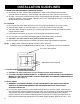
G. BOILER SUPPLY CONNECTIONS
q WARNING: Boiler temperature must be controlled by the boiler high limit not to exceed 200°.
Failure to do so will create a hazardous installation and void the applicable limited warranties.
q All water supply ttings on this heater are brass – do not over tighten or strip threads.
q It is recommended to use a union as per Figures 1 and 2.
NOTE: Be sure to connect Boiler Supply Line (from the boiler) to the “HX in” tting and Boiler
Return Line (to the boiler) to the “HX Out” tting.
H. FILLING THE HEATER
q Check that the temperature-and-pressure relief valve has been properly installed (mandatory
requirement).
q Completely close the drain valve.
q Open the highest hot water faucet to allow air to escape from piping.
q Open the valve to the cold-water inlet and allow the heater and piping system to completely ll, as
indicated by a steady ow of water from the open faucet.
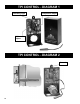
I. TPI THERMOSTAT INSTALLATION
q Attaching TPI Thermostat to tank:
Place hole in back of TPI thermostat over immersion well. TPI thermostat should t ush against the
tank without immersion well protruding beyond cover of TPI case. Use self-tapping screw provided
(Screw A) to attach TPI directly to the Alliance SL tank. (See TPI Diagram 2)
q Inserting the Temperature Sensor:
Slide temperature sensor all the way into the immersion well – until it contacts the end.
(See TPI Diagram 2)
q The sensor will measure temperature adequately by resting against the bottom of the immersion
well.
(Note: Sensor does NOT need to make intimate contact with entire well surface to work properly)
CAUTION: Sensor is soldered directly to TPI. DO NOT BEND SHARPLY OR OVERWORK.
J. TPI WIRING CONTROLS
NOTE: THE TPI CONTROL ELECTRONICS MUST BE POWERED WITH 24VAC.
q Incoming 24VAC power must be connected to 24VAC connectors on the bottom right corner of TPI
Thermostat.
(See TPI Diagram 3)
q The TPI 24VAC only requires 20mA, or about 0.5 Watts.
q Connect control wiring to PUMP/TT normally open relay connections (rated for both 24V and 110V
wiring) on the bottom left corner of TPI control. (See TPI Diagram 3)
q TPI Wiring will vary depending on the type of boiler and valve controls in the system. Consult
attached Wiring Diagrams for appropriate wiring conguration for your system.
q The Alliance SL water heater may operate as a separate heating zone using either the heating
system circulator and an appropriate zone valve, or a separate circulator dedicated for water heating.
(See Figure 1 & 2).
q In both systems, the Alliance SL is controlled through the TPI thermostat on the heater.
(See Figures 1 & 2).
q TPI thermostat calls for the heat when the temperature in the tank is below the set point (120°F) and
either activates a circulator or zone valve depending upon installation design.