INSTALLATION, OPERATING AND SERVICE INSTRUCTIONS FOR Alliance SL™ Indirect - Fired Water Heater Including Warranty Information For service or repairs to the water heater, call your heating contractor. When seeking information on the water heater, provide Model Number and Serial Number as shown on Rating Label. Model Number AL SL Serial Number Heating Contractor Installation Date Phone Number Address U.S. Boiler Company, Inc. 100934-01R1-11/07 Price - $5.
GENERAL INFORMATION PLEASE READ INSTRUCTIONS CAREFULLY BEFORE INSTALLING WATER HEATER U.S Boiler Company, Inc. – Burnham Hydronics (herein called the Company) intends that this Alliance SL™ Indirect-Fired Water Heater be used as a separate zone to a heating system boiler. This appliance is designed to heat water by circulating water from the boiler through the internal coil in the tank. We specifically do not warrant this tank for high temperature applications such as wood stoves or steam producing systems.
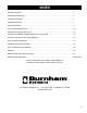
INDEX General Information . .................................................................................................................... 2 Specifications & Ratings . ............................................................................................................. 2 Installation Guidelines .................................................................................................................. 4 Installation Checklist . ............................................................
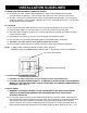
INSTALLATION GUIDELINES A. INSPECTING AND PREPARING THE WATER HEATER q AL27SL thru AL70SL - Remove the cardboard box, which comes packaged with the heater. It should contain the following: TPI thermostat, T&P valve and a “Tee”, foamed lid and screws. q AL119SL - Remove the cardboard boxes, which come packaged with the heater. One box should contain the following: TPI thermostat, T&P valve and a “Tee”, foamed lid and screws. The other box should contain the heat exchanger. B.
valve must be marked with maximum set pressure not to exceed the marked maximum allowable working pressure of the water heater (150psi). Install the valve into the opening provided and marked for this purpose in the water heater, and orient it or provide the tubing so that any discharge from the valve will exit only within 6 inches above, or at any distance below the structural floor and cannot contact any live electrical parts.
q Do not apply heat directly to the cold-water inlet as it is made of plastic and will melt. G. BOILER SUPPLY CONNECTIONS q WARNING: Boiler temperature must be controlled by the boiler high limit not to exceed 200°. Failure to do so will create a hazardous installation and void the applicable limited warranties. q All water supply fittings on this heater are brass – do not over tighten or strip threads. q It is recommended to use a union as per Figures 1 and 2.
q Run all 24VAC wiring thru the square notch on bottom of TPI case. (See TPI Diagram 3) q Incoming 24VAC power must be connected to 24VAC connectors on the bottom right corner of TPI control. (See TPI Diagram 3) q Connect control wiring to PUMP/TT normally open relay connections (rated for both 24V and 110V wiring) on the bottom left corner of TPI control. (See TPI Diagram 3) q All and only 110VAC wiring must go through an appropriate chase nipple installed in the knockout at bottom of TPI case.
q Do not apply heat to cold inlet. q If there is a check valve (sometimes in water meter), backflow preventer or pressure-reducing valve, install an adequate size expansion tank. G. FILLING THE HEATER q Completely fill heater. q Water connections completed and free of leaks. q Check for proper installation of relief valve. q Close drain valve. q Open highest hot water faucet. q Open cold water inlet valve and fill system. H. WIRING See Figure 1 & 2 and separate TPI control wiring diagrams.
WATER TEMPERATURE CONTROLS A periodic inspection of the operating controls, heat exchanger and wiring should be made by qualified service personnel. Temperature of the water should be tested periodically at the faucet to be sure thermostat is working properly. TEMPERATURE ADJUSTMENT The TPI comes with a factory set temperature setting of 120°F and differential setting of 10°F. Any temperature adjustment of the thermostat must be made by qualified service personnel, as shown below.
TPI CONTROL - DIAGRAM 1 Indicating Light Temperature Adjust Differential Adjust TPI CONTROL - DIAGRAM 2 Screw A 10
TPI CONTROL - DIAGRAM 3 Outgoing 24V wires to relay or zone valve Incoming 24V power connection Outgoing 110V wires to circulator Incoming 24V power connections Chase Nipple Conduit NOTE: Use proper conduit and chase nipple 11
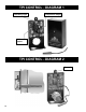
FIGURE 1 - Installation Using Zone Valves Installation Diagram Using Zone Valves FIGURE 2 - Installation Using Circulator Installation Diagram Using Separate Circulator 12
FIGURE 3 - Coil Detail & Tightening Sequence Bolt Small outside O-ring Large inside O-ring Steel Washer Coil Plate Plastic O-Ring Housing Tank Flange ‘L’ Nut Proper Tightening Sequence for Top Mount Coil 7 2 4 3 2 5 6 1 3 1 Incorrect 8 Correct Note: Same as car tire lugs CAUTION: Does not require excessive force to seal properly.
Circulator & Burner Control Wiring Diagrams Standard Wiring for Circulator with Boiler Maintaining a Temperature of 180° ® ® 20° 160° 150° 15° Low Voltage 140° 130° 10° 120 Volts 120° 5° 110° Differential Temperature LED flashing green = calling for heat solid green = at temperature Pump/TT red = error 24v Probe L1 Hot 24v 120 Volts L2 Neutral Switched Hot Circulator Wiring for Burner Control L8148E ® ® 20° 160° TV 150° 15° T W 140° 130° 10° 120° 5° 110° Differential Z Tr
Zone Valve Wiring Diagrams Wiring for 3 Wire Zone Valve Low Voltage ® ® 120 Volts 20° 160° 150° 15° 140° 130° 10° Boiler Connections 120° 5° 110° T Differential T flashing green = calling for heat solid green = at temperature Pump/TT red = error 24v Temperature LED Probe 24v 1 2 3 Hot Zone Valve Neutral 120v Wiring for 4 Zone Valve ® ® 20° 160° 150° 15° 140° 10° 130° 5° 110° 120° Differential LED Motor flashing green = calling for heat solid green = at temperature Pump/T
Switching relay Wiring Diagrams Switching Relay R8845U or SR 501 Switching Relay SR-502 or SR-503 16
Switching relay Wiring Diagrams (con’t) Switching Relay SR-504 with Priority Option ® ® 20° 160° 150° 15° Low Voltage 120 Volts 140° 10° 130° 5° 110° 120° Differential Temperature LED flashing green = calling for heat solid green = at temperature Pump/TT red = error 24v Probe SR 504 ZONE 1 ZONE 2 ZONE 3 ZONE 4 PRIORIT Y ZONE 4 ON OFF POWER FOUR ZONE SWITCHING RELAY WITH OPTIONAL PRIORIT Y ZONE 1 ZONE 2 ZONE 3 ZONE 4 120 VOLT RELAY COM / 24 VAC X X END SWITCH ZONE 1 ZC ZONE 2 Z
HOW TO OBTAIN SERVICE ASSISTANCE U.S. Boiler Company, Inc. – Burnham Hydronics does not have a service department or personnel to service your heater in the field. A qualified installer or service technician must do all service work. Therefore, if you have any questions about your new water heater concerning service adjustment, repair, routine maintenance, or replacement - first contact your installer, plumbing contractor or service agency.
Alliance SL™ Indirect-Fired Water Heater 10/2/1 LIMITED WARRANTY Ten Year Limited Tank Replacement Warranty Two Year Limited Tank Replacement Labor Allowance One Year Limited Parts Warranty U.S. Boiler Company, Inc. – Burnham Hydronics, (hereinafter called the company) offers the following Limited Tank Replacement Warranty, Limited Tank Replacement Labor Allowance, and Limited Parts Warranty to the original purchaser/owner of this stone-lined Alliance SL™ indirect-fired water heater.
ONE (1) YEAR LIMITED PARTS WARRANTY DURATION: The warranty is effective for one (1) year beginning with the date of original purchase. This warranty shall begin from the date of manufacture as indicated by the serial number. COVERAGE: The warranty covers any component part of the Alliance SL™ water heater proven to be defective in workmanship or material. Subject to prior Company approval.
MODEL & SERIAL NUMBER INFORMATION The following information should be noted At time of installation and retained for Future reference. Model No. Serial No. Date Installed Dealer’s Name Address City State Zip U.S. Boiler Company, Inc., – P.O. Box 3079 – Lancaster, PA 17604 www.burnham.
NOTES 22
NOTES 23
Optional Lifetime Warranty Registration Card Available to Residential, Single Family Homes Only Yes, I wish to purchase the Optional Lifetime Warranty! DATE _ _____________________________________________________________________ PURCHASER’S NAME _ _______________________________________________________ HOME ADDRESS ____________________________________________________________ CITY _____________________________ STATE _ _________________ ZIP ______________ HOME PHONE _____________________ EMAIL _______________