
Install Instructions


38
4)AssemblyofZ-FlexZ-VentIII:
a) GeneralNotes:
• Non-expandedendsofSVESeriesIIIpipingsectionsmaybecutusingaviationsnipsora24threadperinch
hacksaw.Fileorsandthecutendsmoothbeforeassembling.ExpandedendsmaybecuttoadapttheSVESeries
IIItotheventcollar.Seethefollowinginstructions.
• Supporthorizontalpipingsectionsatintervalsof48”orless.
• VerticalventingsystemsmustbesupportedbyatleastoneZ-Flexrestop.Anadditionalverticalsupportis
requiredafteranyoffsetandasrequiredbytheZ-VentIIIinstallationinstructions.
b)Startassemblyoftheventsystemattheboiler.RemovethehoseclampshippedontheFCMventcollar.Bendthe
threehoseclamptabsonthiscollaroutwardslightly.
c)Cleantheexteriorofthemaleendoftherstpieceofpipeandtheinsideoftheventcollarontheboiler.Remove
dirt,grease,andmoisturefromthesurfacestobesealed.Drysurfacesorallowtodrythoroughly.
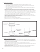
d)Onthemaleendofthepipe,applya¼”widebeadofhightemperaturesiliconeapproximately½inchfromthemale
endofthepipe.Apply¼”beadsofsiliconealongbothsidesofthelongitudinalseam(Figure7.48).
e)Insertthemaleendofthepipeintotheboilerventcollaruntilitbottomsout.
f) Applyanadditionalbeadofsiliconeovertheoutsideofthejointandsmoothout.
g)Replaceandtightentheclampontheventcollar.
h)ThefemaleendofeachZ-VentIIIcomponenthasasiliconesealinggasket.Examineallventcomponentstoinsure
thatthegasketintegrityhasremainedduringshipping.Gasketsmustbeintheproperpositionoruegascouldleak
resultingincarbonmonoxidepoisoning.
i) Alignthesecondpieceofpipewiththerstandpushthemtogetherasfarastheywillgo,butnotlessthan1-3/4”.
j) Tightengearclamptoaminimumtorqueof40in-lbsandamaximumof50in-lbs.
k) RepeatSteps(h)–(j)fortheremainingZ-VentIIIcomponents.
l) Inhorizontalventsystems,alockingbandorgearclampmustbeusedateithersideofthewallpenetrationtoprevent
shiftingoftheventsysteminandoutofthewall.Thisappliestobothcombustibleandnon-combustiblewalls.
n) Allowthesiliconetocureperthesiliconemanufacturer’sinstructionsbeforeoperatingtheboiler.
FIGURE 7.48: Z-VENT III CONNECTION TO VENT COLLAR