
Install Instructions


38
EMP
Installation & Service Manual
109529-03 - 11/19
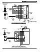
Figure 27: Electrode Settings
2. PRESS RED RESET BUTTON on burner
primary control, hold for ten (10) seconds and
release to reset the control.
3. THE BOILER CONTROL is factory set with a
High Limit setpoint of 190°F. The High Limit
setpoint is adjustable between 100°F and
220°F. This temperature may be varied to suit
the installation requirements.
4. CHECKOUT
Put the system into operation and observe at
least one complete cycle to make sure that the
controller operates properly.
E. CHECK / ADJUST OIL BURNER BEFORE
STARTING.
Natural Vent Applications:
1. Check Burner Settings and readjust if
necessary, see Burner Specifications, Tables
9A and 9B at the rear of this manual. Turn off
power to burner before proceeding.
2. Beckett Burners
a. Remove Gun Assembly.
b. Verify nozzle size, head size, gun setting,
and positioning of electrodes. This
information is shown in Figure 28, and
Beckett AFG Burner Specifications, Table
9A. Replace Gun Assembly.
c. Inspect Beckett head setting on left side
of burner housing by insuring the blue line
MD(V1) or the line on the label MB(L1) are
aligned, readjust if necessary. Refer to
Figure 28 and Table 9A at the rear of this
manual.
d. Check burner air band and air shutter
settings. Readjust if necessary, see Burner
Specifications Table 9A at the rear of this
manual.
e. OPEN ALL SHUT-OFF VALVES in the oil
supply line to the burner.
f. ATTACH A PLASTIC HOSE TO FUEL PUMP
VENT/BLEED FITTING and place the other
hose end into an empty container to catch
the oil.
g. SLIGHTLY OPEN FLAME OBSERVATION
PORT COVER on burner swing door,
enough to insert draft gauge probe later.
3. Carlin Burners
a. Remove nozzle line electrode assembly
from burner.
b. Verify the desired nozzle; refer to Table 9B
at the rear of this manual, for proper nozzle.
The nozzle must be securely installed to
assure leak free joints between the nozzle
and adapter. When installing the nozzle,
be careful not to bump or move the burner
electrodes.
c. Reinstall Flame Retention Head on Nozzle
Line Electrode Assembly. Make sure the
clamp is fully sated against the shoulder on
the nozzle adapter before securing.
d. Loosen and remove the retaining nut and
factory installed head bar from side of
burner housing. Install the proper head bar
that corresponds to the desired firing rate,
refer to Table 9B, and tighten retaining nut.
e. Readjust air band to preliminary setting that
corresponds to the nozzle installed, refer
to Table 9B. Inspect and measure burner
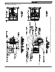
electrodes. Refer to Figure 27 for proper
electrode setting. Readjust electrode setting
to the proper dimensions if necessary.
f. Reinstall nozzle line electrode assembly.
g. Reconnect copper connector tube. Tighten
knurled nut. Close igniter, rotate and tighten
two (2) igniter latching screws.
h. Inspect Carlin head setting on left side
of burner to ensure that the proper head
positioning bar matches the nozzle that is
installed in drawer assembly refer to Table
9B.
Direct Vent Applications:
4. Beckett NX Burners
a. Verify nozzle size, gun setting and
positioning of electrodes. See Figures
29 through 31 and Beckett NX Burner
Specifications, Table 10 at the rear of this
manual.
b. Remove burner cover by loosening the four
thumb screws and set aside.
8 System Start-Up (continued)