
Install Instructions

18
EMP
Installation & Service Manual
109529-03 - 11/19
A. EVALUATE THE EXISTING WATER
SYSTEM.
Design a piping system and install boiler which
will prevent oxygen contamination of boiler water
and frequent water additions.
1. There are many possible causes of oxygen
contamination such as:
a. Addition of excessive make-up water as a
result of system leaks.
b. Absorption through open tanks and fittings.
c. Oxygen permeable materials in the
distribution system.
2. In order to insure long product life, oxygen
sources must be eliminated. This can
be accomplished by taking the following
measures:
a. Repairing system leaks to eliminate the
need for addition of make-up water.
b. Eliminating open tanks from the system.
c. Eliminating and/or repairing fittings which
allow oxygen absorption.
d. Use of non-permeable materials in the
distribution system.
e. Isolating the boiler from the system water by
installing a heat exchanger.
WARNING
System supply and return piping must be
connected to correct boiler manifolds.
U. S. Boiler Company recommends sizing the
system circulator to supply sufficient flow (GPM)
to allow a 20°F temperature differential in the
system. When sizing the system circulator, the
most restrictive single zone should be used to
determine maximum pressure drop.
CAUTION
Maintain minimum ½ inch clearance from hot
water piping to combustible materials.
3. In order to insure long product life, operate boiler
at appropriate flow rate to minimize areas of
overheating
.
a. Design system to ensure that the flow is above
the limit called for in Table 5.
b. Maintain a constant boiler pressure of 12 PSI.
WARNING
Do not operate boiler below minimum volumetric
flow rates.
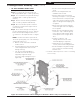
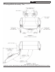
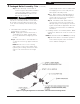
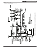
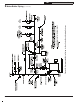
B. CONNECT SYSTEM SUPPLY AND RETURN
PIPING TO BOILER. See Figures 9A and 9B.
Also, consult I=B=R Installation and Piping Guides.
1
. If boiler is used with an Alliance™ SL Indirect Fired
Domestic Water Heater, install the Alliance™ SL as
a seperate heating zone. Refer to the Allaince™ SL
Installation, Operating, and Service Instructions,
for additional information.
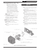
2.
The EMP is designed to withstand thermal shock
from return water temperatures as low as 100ºF,
but prolonged return temperatures of below 135ºF
can cause excessive flue gas condensation and
damage the boiler and/or venting system.
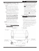
Use a boiler bypass if the boiler is to be operated
in a system which has a large volume or excessive
radiation where low boiler water temperatures
may be encountered (i.e. converted gravity
circulation system, etc.) The bypass should be
the same size as the supply and return lines
with valves located in the bypass and return
line as illustrated in Figures 9A and 9B in order
to regulate water flow for maintenance of higher
boiler water temperature.
3. If it is required to perform a long term pressure
test to the hydronic system, the boiler should
first be isolated to avoid pressure loss due to the
escape of trapped air.
To perform a long term pressure test including
the boiler, ALL trapped air must first be removed
from the boiler.
A loss of pressure during such a test, with no
visible water leakage, is an indication that the
boiler contained trapped air.
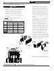
Boiler Model No. Flow Rate (Gal / Min)
EMP84E 4.5
EMP115E 4.5
EMP140E 8.0
EMP182E 10.0
EMP224E 12.0
Table 4: Minimum Flow Rate
3 Water Boiler Piping
NOTICE: Failure to pipe boiler as specified in this
manual may result in excessive system noise.
!
!
!