
Install Instructions

15
EMP
Installation & Service Manual
109529-03 - 11/19
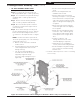
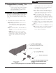
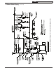
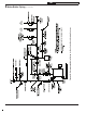
Figure 6: Piping Arrangement for Drain Valve and Indirect Water Heating Return
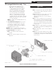
Step c. Pipe discharge of relief valve as
shown in Figures 9A and 9B. Installation
of the relief valve must be consistent
with ANSI/ASME Boiler and Pressure
Vessel Code, Section IV.
WARNING
Safety valve discharge piping must be piped
near floor to eliminate potential of severe burns.
Do not pipe in any area where freezing could
occur. Do not install any shut-off valves, plugs
or caps.
2. Install drain valve and indirect water heater
return piping, see Figure 6.
Step a. Apply pipe sealant to both ends of
1-1/4" NPT x 5" lg. nipple. Thread nipple
into 1-1/4" NPT lower rear tapping on rear
section.
Step b. Thread 1-1/4" x 1-1/4" x 3/4" NPT tee
on opposite end of 5" lg. nipple installed in
Step a.
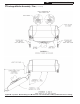
NOTE: Based on access for servicing
and location of sewer or floor drain, when
tightening these fittings, determine if drain
valve is to be located on the left or right
side.
Tighten nipple and tee into 1-1/4" NPT lower
rear tapping or rear section until joints are
water tight for desired position.
Step c. Apply sealant to 3/4" NPT thread on
drain valve. Thread into 3/4" NPT tapping
on side outlet of tee. Use hex nut portion to
tighten valve until water tight.
Step d. If an Alliance™ SL water heater is
connected to system, do not install 1-1/4"
NPT pipe plug. Connect piping as shown in
Figures 9A and 9B, as applicable. Also refer
to Alliance™ SL instructions for additional
information.
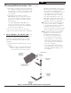
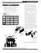
3. Installing stainless steel flueway baffles. Baffle
requirements differ from model to model, see
Table 3.
NOTE: Read caution statement before proceeding.
Step a. Install stainless steel baffles provided
in miscellaneous parts carton as follows,
refer to Table 3 and Figure 7:
2 Packaged Boiler Assembly - Trim (continued)
!