
Install Instructions

11
EMP
Installation & Service Manual
109529-03 - 11/19
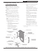
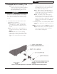
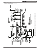
Figure 4A: Partial Front View - Burner Swing Door Mounted to Boiler - Fully Closed and Secured
• Lift door off mounting bracket and set
aside.
• Remove mounting bracket and
hardware from left side.
• Remove upper jacket front panel
retaining screw (5/16” x 1/2” lg. Phillip
Pan head machine screw) from right
side of door and re-install in vacated
upper mounting bracket tapping. Do
not tighten.
• Move lower jacket panel retaining
screw from right side to left tapping.
Do not tighten.
• Rotate door mounting bracket 180°.
Insert 5/16” cap screw through top
hole in bracket and install in upper
vacated jacket hole on right side of
door.
• Install second 5/16” cap
through bracket hole into lower
vacated tapping on right side.
• Tighten both sets of hardware to
secure jacket and mounting bracket.
• Lift door and place integral cast hinge
pins on door into slotted mounting
bracket holes.
2. Perform routine inspection, service or cleaning
as necessary.
2 Packaged Boiler Assembly - Trim (continued)
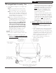
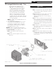
1. TO OPEN BURNER SWING DOOR
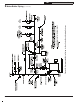
(see Figures 4A and 4B).
Step 1. Loosen but do not remove left side
latching hardware (3/8” x 1-3/4” lg. tap bolt).
Step 2. Loosen and remove right side latching
hardware (3/8” x 1-3/4” lg. tap bolt and
washer).
Step 3. Remove left side latching hardware
(3/8” x 1-3/4” lg. tap bolt and washer).
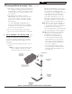
Step 4. Disconnect burner power cord from
receptacle located in lower right corner of
jacket front panel.
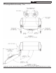
Step 5. Door can be swung to the fully open
position, approximately 90° to 120°, with the
burner mounted providing that there is 19”
of clearance to the adjacent wall, see Figure
1.
NOTE: If reduced clearance prevents the
door from opening fully, one of the following
can provide full access:
a. Burner can be removed to allow full
rotation of door.
b. Door with burner mounted can be lifted
off mounting bracket and set aside
during servicing.
c. The door mounting hardware is
reversible from left side hinge (as
shipped) to right side hinge.
To reverse hinge arrangement (see
Figure 4A):