
Alpine Installation, Operating, and Service Instructions

86
103448-10- 6/18
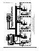
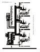
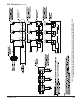
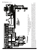
VIII. Electrical (continued)
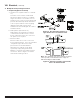
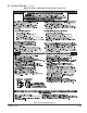
Figure 32: Recommended “Immersion”
Type Header Sensor Installation Detail
Figure 33: Alternate “Strap-On” Type Header
Sensor Installation Detail
Note: The “Strap-On” type sensor must be mounted
to the top side of a horizontal section of pipe as
indicated in Figures 24A and 25A.
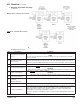
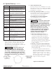
G. Multiple Boiler Operating Information
1. Required Equipment and Setup
a. Header Sensor (P/N 101935-01 or 103104-
01).
A header sensor must be installed and
wired to the Master Sequencer “enabled”
Sage2.X Controller. The header sensor is
installed on the common system piping and
provides blended temperature information
to the Sequence Master. Refer to piping
diagram Figure 24A on page 64 for
installation location and Figure 32 or 33 for
installation detail.
b. RJ45 Splitters (P/N 103192-01)
RJ45 Splitters are required for installing
communications between three or more
boilers. When two boilers are connected
the splitter is not required.
c. Ethernet Cables
Ethernet cables are used to connect the
boiler network together. These are standard
“straight through” cables that can be
purchased at electrical distributors.
Alternately, the network can be wired
together by simply wiring terminal J3,
Modbus 2, terminals A, B and V- between
each boiler. Refer to Figures 27 and 28
terminal J3 for wiring location.