
Alpine Installation, Operating, and Service Instructions

103448-10 - 6/18 19
3. Vent/Combustion Air Terminals
Install venting system components on exterior of building only as specifically required by these instructions
(refer to Figure 4).
a. Use only listed vent/combustion air terminals.
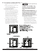
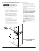
i. Horizontal Sidewall Venting: For models ALP080B thru ALP285B, use coupling for vent terminal and
90° elbow for combustion air intake terminal as shown in Figure 5). Alternate staggered and snorkel
terminations are shown in Figure 6A and Figure 6B.
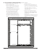
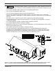
ii. Vertical Roof Venting: Use straight coupling on vent and two 90° elbows turned downwards for
combustion air as shown in Figure 7A. and Figure 8).
iii. For Alpine boilers factory build prior to January 2016, US Boiler provided PVC tees (3” or 4” as
applicable to specific boiler model) to be used either as vent or air intake terminals.
For Alpine boilers factory build after January 2016, US Boiler provides PVC coupling (2”, 3” or 4” as
applicable to specific boiler model) to be used as vent terminal and PVC 90° elbow (2”, 3” or 4” as
applicable to specific boiler model) to be used as air intake terminal.
Both above listed combinations of vent/air intake terminations are approved/permissible to use per
Intertek Alpine Listing Report No. 3132672CRT-04.
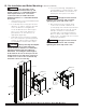
b. Maintain correct clearance and orientation between vent and combustion air terminals.
i. Space center lines of vent and combustion air terminals minimum 12 in. (300 mm) apart. Spacing of
more than 12 in. (300 mm) is recommended.
ii. If possible, locate vent and combustion air terminals on the same wall to prevent nuisance shutdowns.
If not, boiler may be installed with roof vent terminal and sidewall combustion air terminal.
iii. When installed on the same wall, locate vent terminal at same height or higher than combustion air
terminal.
iv. When using tee terminals, do not locate vent terminal directly above air intake as dripping condensate
may freeze on and block intake.
c. Locate bottom of vent and combustion air terminals at least 12 in. (300 mm) [18 in. (460 mm) in Canada]
above the normal snow line and at least 12 in. (300 mm) above grade level.
d. Locate vent and combustion air terminals at least 12 in. (300 mm) from any door, window, or gravity inlet
into the building.
e. Do not install vent terminal directly above windows or doors.
f. Locate bottom of vent terminal at least 3 ft. (900 mm) above any forced air inlet located within 10 ft. (3.0
m).
g. If window and/or air inlet is within 4 ft. (1.2 m) of an inside corner, maintain at least 6 ft. (1.8 m) spacing
between terminal and adjoining wall of inside corner.
h. Locate bottom of vent terminal at least 7 ft. (2.1 m) above a public walkway.
i. Maintain minimum clearance of at least 4 ft. (1.22 m) [6 ft. (1.83 m) in Canada] horizontally from, and in no
case above or below electric meters, gas meters, regulators, and relief equipment.
j. Do not locate the vent terminal under decks or similar structures.
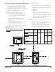
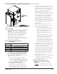
k. Top terminal must be at least 24 in. (609.6 mm) below ventilated eves, soffits and other overhangs. In no
case may the overhang exceed 48 in. (1219.2 mm). Where permitted by the authority having jurisdiction
and local experience, the terminal may be located closer to unventilated soffits. The minimum vertical
separation depends upon the depth of the soffit. See Figure 4 for details.
l. Maintain minimum 12 in. (300 mm) horizontal spacing between vent terminal and a building corner.
m. Under certain conditions, water in the flue gas may condense, and possibly freeze, on objects around the
terminal including on the structure itself. If these objects are subject to damage by flue gas condensate,
they should be moved or protected.
n. If possible, install the vent and combustion air terminals on a wall away from the prevailing wind. Reliable
operation of this boiler cannot be guaranteed if terminals are subjected to winds in excess of 40 mph (64
km/hr).
o. Do not locate combustion air terminal in areas that might contain combustion air contaminates, such as
near swimming pools.
IV. Venting A. General Guidelines (continued)