
User guide

42 - 8645
English
The system is live. Working on the unit involves acute risk of injury.
Always switch off the power supply before starting work!
Observe all applicable accident prevention and safety regulations for electrical equipment.
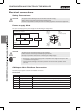
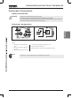
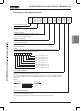
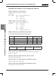
The 4-pin round plug for the power supply has the following pin assignments:
Electronics Inputs
Outputs
24 V DC (1) Outputs
24 V DC (2)
Logic
G
ND ()
Logic
GND (4) Outputs
PIN 1
+24 V
driver (outputs)
PIN 4
GND
driver
PIN 2
+24 V
Logic
PIN
GND
Logic
Illustration: Power supply M12 - Fieldbus module CANopen
The slots for bus and voltage supply can be confused.
If these slots are confused, you risk destroying the device.
Use only a 4-pin M12 connector for connecting the voltage supply.
• Protect pin 1 of the power supply with 4 A (medium time-lag) fuse and pin 2 with
1 A (medium time-lag) fuse.
• FE (functional earthing) to the earth potential with the shortest possible cable
(0 cm).
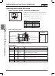
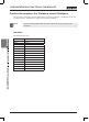
The M12 plug-in system is used for the fieldbus connection.
1 Screen Screen or protective earth
2 CAN_V+ (n. c.) Lines are looped through, current bearing capacity max. 4 A
GND Data transmission potential (reference potential CANopen)
4 CAN High CAN High line
5 CAN Low CAN Low line
Thread Screen Screen or protective earth