
Owner manual
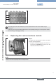

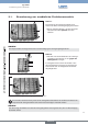
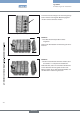

Connect added modules to the existing valve
→
terminal by pressing and then turning the three
locking through 90°.
The depression of the locking pins can be facili-
tated by pressing the module onto the existing valve
terminal.
The slot is vertical.
→
Attaching more modulesFig. 19:
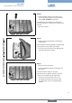
Push the blue locking bracket over the desig-
→
nated guides.
Ensure that the connecting bracket is inserted neatly
into the guides and is pushed down parallel.
To do this, support the bracket by gripping both
→
lugs and push all the way down.
Attaching the locking bracketFig. 20:
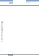
E-rails must be re-attached.
→
Connect additional modules accordingly to the →
FE contact.
The valve terminal is ready for use again.
Remember that any address setting on the head
module must be adjusted to the original state.
To do this, open the window on the corre-
→
sponding head module and, using the rotary
encoding switch, set the corresponding bus
address.
Valve terminal ready for useFig. 21:
english