
Owner manual
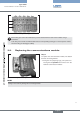


Detach any FE rails from the back of the valve
→
terminal.
Detach the module to be replaced from the wall
→
or top hat rail.
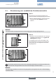
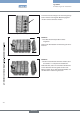
Then release and disengage the 3 locking pins by
→
turning them through 90°.
In the released position the slots in the locking pins
are horizontal. The locking pins project over the
contact surface of the connecting bracket.
Releasing the locking pinsFig. 16:
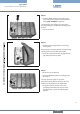
By applying gentle lateral pressure to the exposed side areas of the valve terminal in the vicinity of the cor-
responding locking pins, they can be supported as they are snapped out.
If the modules are removed without disengaging the locking pins, the modules may be damaged.
By snapping out the three locking pins, the head
module is released from the valve terminal and can
be removed without difficulty.
To do this, remove the head module parallel from
→
the side of the terminal.
Removing the head moduleFig. 17:
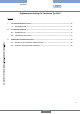
To attach the new head module, proceed in reverse
sequence.
First grease the seals and O-rings on the module.
→
Then press the module onto the side of the valve →
block.
Ensure that O-rings, seals and electrical plug-and-
socket connections are not damaged.
Attaching the head moduleFig. 18:
english