
Owner manual
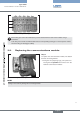

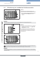
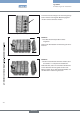

Aid when releasing the locking pinsFig. 14:
If the locking pins cannot be released, they can be released from the back of the modules using a
screwdriver.
To do this, press a small screwdriver blade onto the corresponding locking pin on the respective module
until the locking pin disengages audibly.
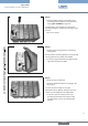
To replace the communications module, first detach
the blue connecting bracket.
Using the two projecting lugs, pull up blue con-
→
necting bracket and remove from the
interface to the function modules.
Attaching the connecting bracketFig. 15:
Pulling on one side may damage the connecting bracket!
english