
Owner manual


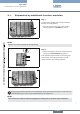
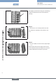

Push the blue locking bracket over the desig-
→
nated guides.
Ensure that the connecting bracket is inserted neatly
into the guides and is pushed down .
To do this, support the bracket by gripping both
→
lugs.
Attaching the connecting bracketFig. 10:
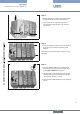
If more modules are to be added, repeat steps
→
5 – 8.
In doing so, note the appropriate system limits. To
close the valve terminal, attach the cover module
which fits the corresponding head module.
Attach cover module by pressing parallel on the
→
valve terminal.
Ensure that O-rings, seals and electrical interface are
not damaged.
Attaching more modulesFig. 11:
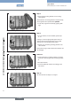
Lock locking pins according to Step 7 and push
→
down blue connecting bracket according to Step
8.
Re-attach FE rails.
→
Connect additional modules accordingly to the →
FE contact.
Attaching the connecting bracketFig. 12:
The valve terminal is ready for use again!
Valve terminal ready for useFig. 13:
english