
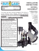
Instruction Manual
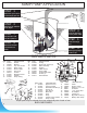

REPAIR PARTS
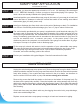
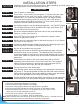
STEP 2
Sump pit 18” diameter
X 25” depth
STEP 3
Determine your choice
of discharge pipe size
STEP 4
Install your pump in
centre of pit
STEP 5
Install discharge
pipe
STEP 7
Fill the basin and
test the operation
STEP 8
Review and check
connections for
leaks
REF. PART DESCRIPTION
1 310412 Handle
2 300450 Bearing
3 310414 Top cover screws
4 310415 Motor casing
5 310416 Rotor & shaft
6 310418 Seal cover
7 350311 Oil seal
8 310420 Mechanical seal
9 310421 Impeller
10 310422 Pump casing
SUMP PUMP APPLICATION
Repair parts may be ordered from your authorized point of sale or from
BUR-CAM PUMPS
6
STEP 6
Connect float and
motor power cable
REF. PART DESCRIPTION
11 310424 O-Ring
12 310423 Pump body screws (6)
13 310425 Stator assembly
14 310426 Packing
15 310427 Cable screws
16 310428 Power cable
17 450447 Vertical float switch
18 450402 Screws (4)
19 310411 Switch braket
REF. PART DESCRIPTION
1 310660 Upper box cover
2 310661 Lower box base
3 310672 Alternative handles (2)
4 310667 Screws (4)
5 310673 PVC ties (4)
6 310670 Black belt
7 310666 Float
8 310659 Pump
9 310676 Impeller & lock washer
10 310677 Pump O -Ring
REF. PART DESCRIPTION
11 310663 Volute
12 310662 Suction screen
13 52259 Reducer 1” to 1 1/4”
14 52258 90° Elbow
15 350353 1 1/4” check valve
16 310665 AC Adaptor
17 310664 Control box
18 310668 Big head screws (4)
19 310671 Battery cable clamp
Model 300403H 2007
1
2
3
4
5
6
17
7
15
18
19
14
16
13
8
9
10
11
12
2
3
4
5
12
6
7
8
9
16
15
14
13
11
10
1
17
18
19