CEZ CDBC TWIN N IO UT CA C A U T IO N : ! DISCONTINUED VERSION The information in this manual is no longer current. N IO UT CA C A U T IO N : ! N IO UT CA C A U T IO N : ! OPERATING & SERVICE MANUAL BUNN-O-MATIC CORPORATION POST OFFICE BOX 3227 SPRINGFIELD, ILLINOIS 62708-3227 PHONE: (217) 529-6601 FAX: (217) 529-6644 29319.0000D 09/03 ©1999 Bunn-O-Matic Corporation www.bunnomatic.
INTRODUCTION This equipment will brew one or two half-gallon batches of coffee simultaneously into awaiting dispensers with just the press of a button. One side may include a hot water faucet for allied beverage use. Most functions of the brewer are digitally controlled. It is only for indoor use on a sturdy counter or shelf. CONTENTS Introduction & Warranty .................................................................................... 2 User Notices ..................................................
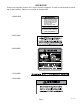
USER NOTICES Carefully read and follow all notices in this manual and on the equipment. All labels on the equipment should be kept in good condition. Replace any unreadable or damaged labels. # 00986.0000 ! WARNING DO NOT OVERLOAD CIRCUIT. ALWAYS ELECTRICALLY GROUND THE CHASSIS OR ADAPTOR PLUG. DO NOT DEFORM PLUG OR CORD. FOLLOW NATIONAL AND LOCAL ELECTRICAL CODES. KEEP COMBUSTIBLES AWAY. FAILURE TO COMPLY RISKS EQUIPMENT DAMAGE, FIRE OR SHOCK HAZARD.
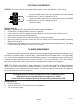
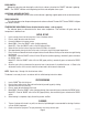
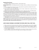
ELECTRICAL REQUIREMENTS CAUTION - The brewer must be disconnected from the power source until specified in Initial Set-Up. L2 RED 120V.A.C. WHITE 208 or 240V.A.C. NEUTRAL L1 BLACK 120V.A.C. One circuit models require one 3-wire, grounded service rated 120/208 or 120/240 volts ac, 40 amp, single phase, 60 Hz. Two circuit models require two 3-wire, grounded service rated 120/208 or 120/240 volts ac, 20 amp, single phase, 60 Hz.
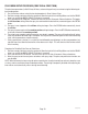
OPERATING CONTROLS Model CEZ TWIN ON/OFF BREW FRONT-SIDE-REAR ON/OFF BREW FRONT-SIDE-REAR P1870 ON/OFF SWITCH Placing the "ON/OFF" switch in the "ON" upper position supplies power to the brew station warmer, enables the brew circuit, and energizes the tank refill circuit. Placing the switch in the "OFF" lower position stops tank refilling, brewing and deenergizes the brew station warmer.
BREW SWITCH Momentarily pressing and releasing the switch starts a brew cycle when the "ON/OFF" indicator is glowing. NOTE – The "ON/OFF" indicator must be glowing to initiate and complete a brew cycle. ADDITIONAL WARMER SWITCHES Pressing any additional warmer switch so the indicator is glowing, supplies power to the associated warmer. READY INDICATOR This indicator glows when the preset temperature has been achieved. The word "NOT" above "READY" will glow in all other instances.
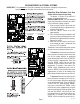
CEZ ADJUSTMENTS & OPTIONAL SETTINGS IMPORTANT: The tank must be full and refill solenoid shut off prior to making these adjustments. Sprayhead must be installed while making these adjustments. Adjusting Brew Volumes (Each Brew TRM1 COUNTER TRM2 + J7 READY LED + + J3 J6 LOCK UNLOCK J1 BOM PART NO.
CDBC ADJUSTMENTS & OPTIONAL SETTINGS HIDDEN HIDDEN SWITCH SWITCH P1871 NOTE: The following adjustments must be performed for each Brew Station. Setting Brew Temperature The brewer is factory set to brew at 200°F(95°C). To change this setting, press and hold the "HIDDEN" switch beneath the "®". The word "TEMP" above the "ON/OFF" switch will glow to correspond with the temporary function change of this switch.
Adjusting Brew Volumes The brewer is factory set to deliver 64 ounces ± 2 for each brew cycle. BREW VOLUME SET-UP: Use the following steps when the setting is unknown or a different circuit board is being installed. 1. Place an empty funnel in the funnel rails and an empty decanter or graduated vessel beneath the funnel. 2. Press the "ON/OFF" switch (indicator glowing). 3. Press and hold the brew start button until you hear the brew solenoid click on-and-off three times (approximately 10 seconds).
PULSE BREW SETUP PROCEDURE (CDBC TWIN & CDBCF TWIN) The pulse brew parameters (initial fill time, off times, and remaining on times) are entered using the following setby-example process. 1. First set the brew volume using the standard procedure in Brew Volume Setup. 2. Position an empty container under the sprayhead. Allow the tank to finish refilling. Make sure that the READY lamp is on, or that the BREW LOCKOUT function is turned off. 3. Press and hold the OFF/ON button.
TROUBLESHOOTING A troubleshooting guide is provided to suggest probable causes and remedies for the most likely problems encountered. If the problem remains after exhausting the troubleshooting steps, contact the Bunn-O-Matic Technical Service Department. • • • • • • • Inspection, testing, and repair of electrical equipment should be performed only by qualified service personnel. All electronic components have 120 volt ac and low voltage dc potential on their terminals.
TROUBLESHOOTING (cont.) REFILL CIRCUIT PROBLEM PROBABLE CAUSE Will not fill or refill 1. Power off to brewer (CDBC & CEZ) Press warmer switches on control panel to determine if power is ON. 2. Water shut off (CDBC & CEZ) Make sure water is ON. 3. Display flashing (CDBC) or ready light flashing (CEZ) Brewer has shut down due to malfunction (See Diagnostic Chart in manual, Page 20, or under top lid of brewer). 4. ON/OFF Switch (CDBC & CEZ) Make sure ON/OFF Switch is "ON" and indicator is lit. 5.
TROUBLESHOOTING (cont.) REFILL CIRCUIT (cont.) PROBLEM Fill or refill does not shut "OFF" (ON/OFF Switch "OFF") PROBABLE CAUSE REMEDY 2a. Water Level Probe Sensing System (CDBC) A) Disconnect the brewer from the power source. Disconnect the J3 connector from the control board. Check for continuity from the nut on top of the level probe to pin 1 of the plug, continuity should be present. Pull the temperature probe up about an inch from the grommet.
TROUBLESHOOTING (cont.) HEATING CIRCUIT PROBLEM PROBABLE CAUSE REMEDY Water does not heat to proper temperature 1. Display flashing (CDBC) or ready light flashing (CEZ) Brewer has shut down due to malfunction (See Diagnostic Chart in manual, Page 20, or under top lid). 2. Water not touching temperature probe Remove probe and grommet. Look into hole on tank lid. Water must be within one inch from top of tank. 3a. Dry Plug In Probe Sensing System (CDBC) A) Disconnect the brewer from the power source.
TROUBLESHOOTING (cont.) HEATING CIRCUIT PROBLEM PROBABLE CAUSE REMEDY Water does not heat to proper temperature (cont.) 4a. Temperature Probe (CDBC) A) Remove the probe from the grommet and submerge in a water bath of approximately 70°F(21°C). Connect an ohmmeter to pins 3 and 4 of the J3 connector. At 60°F(16°C) the reading should be 15.3k ± 2k OHMS, at 70°F(21°C) the reading should be 11.8k ± 2k OHMS, and at 80°F(27°C) the reading should be 9.3k ± 2k OHMS.
TROUBLESHOOTING (cont.) HEATING CIRCUIT PROBLEM PROBABLE CAUSE REMEDY Spitting or excessive steaming (cont.) 2a. Temperature Probe (CDBC) A) Remove the probe from the grommet and submerge in a water bath of approximately 70°F(21°C). Connect an ohmmeter to pins 3 and 4 of the J3 connector. At 60°F(16°C) the reading should be 15.3k ± 2k OHMS, at 70°F(21°C) the reading should be 11.8k ± 2k OHMS, and at 80°F(27°C) the reading should be 9.3k ± 2k OHMS.
TROUBLESHOOTING (cont.) BREWING CIRCUIT PROBLEM PROBABLE CAUSE REMEDY Brew cycle will not start 1. Display flashing (CDBC) or ready light flashing (CEZ) Brewer has shut down due to malfunction (See Diagnostic Chart in manual, Page 20, or under top lid of brewer). 2. No water Water lines and valves to the brewer must be open. 3. No power or incorrect voltage to the brewer Check for voltage across the black and white terminals at the terminal block. 4.
TROUBLESHOOTING (cont.) BREWING CIRCUIT (cont.) PROBLEM PROBABLE CAUSE REMEDY Brew cycle will not start (cont.) 8. Control board or dispense valve (CDBC & CEZ) If the start switch (CEZ) or switch panel (CDBC) is operating properly, proceed as follows. Attach a voltmeter to the terminals of the dispense solenoid. Connect the brewer to the power source. Turn on the brewer and press the BREW switch. Voltage should be present at the solenoid terminals.
TROUBLESHOOTING (cont.) BREWING CIRCUIT (cont.) PROBLEM PROBABLE CAUSE REMEDY Dripping from sprayhead 1. Lime build up Inspect the tank assembly for excessive lime deposits. Delime as required. 2. Dispense valve Remove the dispense valve and clear any obstructions. Rebuild or replace the valve if necessary.(See page 27) 1. Sprayhead A six-hole stainless steel sprayhead must be used for proper extraction. 2. Water temperature Place an empty brew funnel on an empty decanter beneath the sprayhead.
TROUBLESHOOTING (cont.) BREWING CIRCUIT (cont.) PROBLEM PROBABLE CAUSE REMEDY Dry coffee grounds remain in the funnel 1. Sprayhead Make sure sprayhead is present and holes are clear and unobstructed. There should be six separate streams of water coming out of the sprayhead. 2. Funnel loading The BUNN® paper filter must be centered in the funnel and the bed of grounds leveled by shaking gently. 1. Warmer Disconnect the brewer from the power source.
DIAGNOSTICS Intermittent flashing of the READY indicator (Model CEZ) or the bank of temperature indicators (Model CDBC) indicates that a fault exists. Count the number of flashes between pauses and use this chart as a guide to investigating the fault.
SERVICE This section provides procedures for testing and replacing various major components used in this brewer should service become necessary. Refer to Troubleshooting for assistance in determining the cause of any problem. WARNING - Inspection, testing, and repair of electrical equipment should be performed only by qualified service personnel. The brewer should be unplugged when servicing, except when electrical tests are required and the test procedure specifically states to plug-in the brewer.
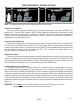
SERVICE (cont.) PC CONTROL BOARD - Model CDBC ! ER N IO CANT UT D DE CA DISCAR D Y KE D PT AC HEY . CRRATCDR EN EM ME IC D . SC ILE WH H FLATR EC . BOATED HIG EL ONSED . HEED US PO IF: . EX TS RY . OREMEN N JU EL TS S IN PORATIO EN SK COR RI NT TIC CO T LY -MA MP EL N-O NN E HO CO 5 BUN FU AR 198 TO RE ILU FA 658 C A U T IO N : PN: P1873 FIG. 2 CONTROL BOARDS - CDBC Location: The Control Boards are located inside the top cover behind the front end caps.
SERVICE (cont.) PC CONTROL BOARD - Model CEZ J1 1 TRM 2 TRM J2 J3 R EA E-R ID T-S ON FR E H O T J5 R A S E C S D N W A R M E R S A J1 U R F A J4 T AR ST R WE /LO ON IO N : J6 T 1 C A U TRM 2 J7 TRM J2 J3 R EA -R IDE T-S ON FR E H O T J5 R A S E C W A R M E R S A N D S U R F A J4 T AR ST R WE /LO ON C A U T IO N : J6 C A U T IO N : C A U T IO N : J7 P1874 FIG.
SERVICE (cont.) SWITCH PANEL - Model CDBC ! CA N ER NT CA D DE AR DISC IF: KED D Y UT IO PT AC HEY . CRRATCDR EN EMAME IC D . SC ILE WH H FL TR EC . BOATED HIG EL ONSED . HEED PO . US EX TS RY . OREMEN JU ION EL RAT S IN TS EN RPO NT RISK TIC CO CO T LY -MA EL MP N-O NN E HO CO 5 BUN FU AR 198 E TO ILUR FA 658 C A U T IO N : C A U T IO N : PN: P1875 FIG. 4 SWITCH PANELS - CDBC Location: The Switch Panels are located on the front of the hood. Removal and Replacement: 1.
SERVICE (cont.) ON/OFF SWITCHES - Model CEZ If continuity is present as described, reconnect the black wire to the center terminal and the remaining wire to the lower terminal. If continuity is not present as described, replace the switch.
SERVICE (cont.) BREW SWITCH (Start) - Model CEZ J1 If continuity is present as described, reconnect the white/yellow wire to the top terminal and the white/ orange to the bottom terminal. If continuity is not present as described, replace the switch. M1 TR M2 TR J2 Removal and Replacement: 1. If switch to be removed is in the left control panel and brewer is equipped with a faucet, turn off water supply and remove faucet. 2. Remove front end cap. 3.
SERVICE (cont.) DISPENSE VALVE 6. Connect the voltmeter lead ends to the dispense valve coil terminals. Connect the brewer to the power source. Brewer temperature lockout must be disabled. Place "ON/OFF" Switch in the "ON" position. Press and release the brew switch. The indication must be 120 volts ac for two-wire 120 volt models and three-wire 120/208 volt models. 7. Disconnect the brewer from the power source.
SERVICE (cont.) LIMIT THERMOSTAT J1 Removal and Replacement: 1. Remove the black and blue wires from limit thermostat terminals. 2. Carefully slide the limit thermostat out from under the retaining clip and remove limit thermostat. 3. Carefully slide the new limit thermostat into the retaining clip. 4. Refer to FIG. 12 when reconnecting the wires.
SERVICE (cont.) TANK HEATERS If continuity is present as described, reconnect the wires, the tank heater is operating properly. If continuity is not present as described, replace the tank heater. NOTE- If the tank heater remains unable to heat, remove and inspect heater for cracks in the sheath. P1855 FIG. 13 TANK HEATER Location: The tank heaters are located inside the tanks and secured to the tank bottoms. Test Procedures: 1. Disconnect the brewer from the power supply. 2.
SERVICE (cont.) TANK HEATERS (Cont.) 17. Install tank assembly onto mounting brackets and secure in place with four #8-32 nuts. 18. Install tank lid and secure in place with eight #8-32 nuts. 19. Connect the two white wires of the tank warmer blanket. 20. Connect the limit thermostat to the front of the tank assembly. 21. Connect the green wire to the tank mounting bracket using #8-32 nut. 22. Connect the pink wire to the level probe. 23. Insert the temperature probe through the grommet in the tank lid. 24.
SERVICE (cont.) REFILL VALVE J1 6. Check the refill valve for coil action. Connect the brewer to the power source. With "ON/OFF" switch in the "ON' upper position press start switch and listen carefully in the vicinity of the refill valve for a" clicking" sound as the coil magnet attracts. 7. Disconnect the brewer from the power source.
SERVICE (cont.) WARMER ELEMENT(S) 5. Check the continuity across the two terminals on the warmer element. If continuity is present as described, reconnect the two wires to the warmer element. If continuity is not present as described, replace the warmer element. ! CA UT IO N RD CA DIS D IF: ER NT CA DE TY CKEHED . CRAATCDRYEN EMPME IC . SCRLED WH H FLA CTR . BOI TED HIG ELE ON D . HEAD OSE . USEEXP TS Y UR .
Page 34 29319 091203 B O A R D C P C O N T R O L t° P R O B E L E V E L P1, P2, & P3 ARE PINS OF A POLARIZED THREE-PIN CONNECTOR. GRY BLK WHI/RED WHI/YEL BLK WHI GRN PNK WHI/ORA WHI/BLU WHI/GRN 120/208V AC 3 WIRE 120/240V AC 3 WIRE SINGLE PHASE J7-1 J7-2 J5-6 J1-8 J5-1 BLU-14 COUNTER (OPTIONAL) WHI BLK TRM-1 TRM-2 BLK BLU-14 COM N.O.
Page 35 29319 091203 B O A R D C P C O N T R O L J3-4 J3-1 J2-11 J2-6 J2-1 J1-10 J1-5 BLK PNK GRN WHI COUNTER (OPTIONAL) BLU-14 STATIC SHIELD HIDDEN SW ON/OFF SW t° LEVEL PROBE REFILL WHI C O N T R O L LIMIT THERMOSTAT BLU-14 L1 WHI/VIO YEL SOL W H I WHI WHI/BLU P1 WHI WHI WHI WHI P1, P2, & P3 ARE PINS OF A POLARIZED THREE-PIN CONNECTOR. SOL WHI 29323.
Page 36 29319 091203 B O A R D C P C O N T R O L J3-4 J3-1 J2-11 J2-6 J2-1 J1-10 J1-5 BLK PNK GRN WHI COUNTER (OPTIONAL) BLU-14 STATIC SHIELD HIDDEN SW ON/OFF SW t° LEVEL PROBE TOP FRNT SW REFILL VIO P1 WHI/BLU WHI WHI WHI WHI P1, P2, & P3 ARE PINS OF A POLARIZED THREE-PIN CONNECTOR. SOL WHI 29323.