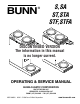
BUNN ® S,SA ST,STA STF,STFA DISCONTINUED VERSION The information in this manual is no longer current. OPERATING & SERVICE MANUAL BUNN-O-MATIC CORPORATION POST OFFICE BOX 3227 SPRINGFIELD, ILLINOIS 62708-3227 PHONE: (217) 529-6601 FAX: (217) 529-6644 29251.0000G 04/01 ©1998 Bunn-O-Matic Corporation www.bunnomatic.
WARRANTY Bunn-O-Matic Corp. (“Bunn”) warrants the equipment manufactured by it to be commercially free from defects in material and workmanship existing at the time of manufacture and appearing within one year from the date of installation. In addition: 1.) Bunn warrants electronic circuit and/or control boards to be commercially free from defects in material and workmanship for three years from the date of installation. 2.
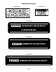
USER NOTICES (Continued) #00882.0000 #00656.0000 #02763.0000 #02765.0000 #02769.
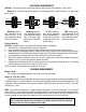
ELECTRICAL REQUIREMENTS CAUTION - The brewer must be disconnected from the power source until specified in Initial Set-Up. Model 15 has an attached cordset and requires 2-wire grounded service rated 120 volts ac, 15 amp, single phase, 60 Hz. L2 RED WHITE NEUTRAL L1 BLACK WHITE 120V.A.C. NEUTRAL WHITE 120V A.C. 208 or 240V.A.C. 120V A.C. NEUTRAL L1 BLACK 100V.A.C. L1 BLACK P2185 Model 20 requires 2wire, grounded service rated 120 volts ac, 20 amp, single phase, 60 Hz.
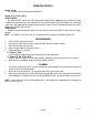
INITIAL SET-UP CAUTION - The brewer must be disconnected from the power source throughout the initial set-up, except when specified in the instructions. 1. 2. 3. Insert an empty funnel into the funnel rails. Place an empty dispenser under the funnel. Remove the front or rear panel and turn the thermostat knob to the “OFF” position and connect the brewer to the power source. 4. Fill the tank with water as directed: 4A.
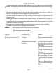
OPERATING CONTROLS Models S & SA: These models function without operating controls. Models ST, STF, STA & STFA: ON/OFF SWITCH Placing the "ON/OFF" switch in the "OFF" lower position stops brewing. Stopping a brew cycle after it has been started will not stop the flow of water into the funnel until the tank syphons down to its proper level. Placing the switch in the "ON" upper position supplies power to the brew station warmer and enables the brew circuit and on Models STF and STFA refills the tank.
TROUBLESHOOTING A troubleshooting guide is provided to suggest probable causes and remedies for the most likely problems encountered. If the problem remains after exhausting the troubleshooting steps, contact the Bunn-O-Matic Technical Service Department. • • • • • • • Inspection, testing, and repair of electrical equipment should be performed only by qualified service personnel. All electronic components have 120 volt ac and low voltage dc potential on their terminals.
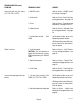
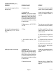
TROUBLESHOOTING (cont.) PROBLEM PROBABLE CAUSE REMEDY Brew cycle will not start (cont.) (ST, STF, STA & STFA) 3. ON/OFF switch Refer to Service - ON/OFF Switch for testing. See page 17 4. Start switch Refer to Service - Start Switch for testing procedures. See page 19 5. Timer Refer to Service - Timer for testing procedures. See page 22 or 24 6. Solenoid valve Refer to Service - Solenoid Valve for testing procedures. See page 18 7. Strainer/flow control GPM) (.
TROUBLESHOOTING (cont.) PROBLEM PROBABLE CAUSE REMEDY Inconsistent beverage level in dispenser (cont.) 3. Syphon system The brewer must be level or slightly lower in front to syphon properly. 4. Lime build-up CAUTION - Tank and tank components should be delimed regularly depending on local water conditions. Excessive mineral build-up on stainless steel surfaces can initiate corrosive reactions resulting in serious leaks. Inspect the tank assembly for excessive lime deposits. Delime as required. 5.
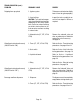
TROUBLESHOOTING (cont.) PROBLEM PROBABLE CAUSE REMEDY Dripping from sprayhead 1. Syphon system The brewer must be level or slightly lower in front to syphon properly. 2. Lime build-up CAUTION - Tank and tank components should be delimed regularly depending on local water conditions. Excessive mineral build-up on stainless steel surfaces can initiate corrosive reactions resulting in serious leaks. Inspect the tank assembly for excessive lime deposits. Delime as required. 3.
TROUBLESHOOTING (cont.) PROBLEM PROBABLE CAUSE REMEDY Beverage overflows dispenser (cont.) 3. Solenoid valve (ST, STF, STA & STFA) Remove the Solenoid Valve and clean any obstruction. Rebuild or replace the valve if necessary. See page 18 Weak beverage 1. Filter type The BUNN® paper filter must be used for proper extraction. 2. Coffee grind A fine or drip grind must be used for proper extraction. 3. Sprayhead A six-hole stainless steel sprayhead must be used for proper extraction. 4.
TROUBLESHOOTING (cont.) PROBLEM PROBABLE CAUSE REMEDY Brewer is making unusal noises (ST, STF, STA & STFA)(cont.) 3. Water supply (A) The brewer must be connected to a cold water line. (B) Water pressure to the brewer must not exceed 90 psi (620 kPa). Install a regulator if necessary to lower the working pressure to approximately 50 psi (345 kPa). Automatic refill will not operate 4. Tank heater Remove and clean lime off the tank heater. See page 20 1. No water Check plumbing 2.
SERVICE This section provides procedures for testing and replacing various major components used in this brewer should service become necessary. Refer to Troubleshooting for assistance in determining the cause of any problem. WARNING - Inspection, testing, and repair of electrical equipment should be performed only by qualified service personnel. The brewer should be unplugged when servicing, except when electrical tests are required and the test procedure specifically states to plug-in the brewer.
SERVICE (cont.) CONTROL THERMOSTAT BU OFF Test Procedures: 1. Disconnect the brewer from the power source. 2. Locate the blue wire on the control thermostat. 3. Check the voltage across the blue wire on the control thermostat and the white insert on two pole 100 or 120 volt terminal block or three pole 120/240 volt terminal blocks and the red insert on two wire 200 volt or 240 volt terminal block with a voltmeter. Connect the brewer to the power source.
SERVICE (cont.) NOTE - The capillary tube must be clear of any electrical termination and not kinked. 7. 8. 9. Models S & SA: Using two #8-32 screws secure the control thermostat inside the rear inspection panel. Models ST, STA, STF & STFA: Using one #8-32 screw secure the control thermostat to the component bracket inside the front inspection panel. Refer to FIG. 3 when reconnecting the wires. Adjust the control thermostat as required.
SERVICE (cont.) LIMIT THERMOSTAT Removal and Replacement: 1. Remove all wires from limit thermostat terminals. 2. Carefully slide the limit thermostat out from under the retaining clip and remove limit thermostat. 3. Carefully slide the new limit thermostat into the retaining clip. 4. Refer to FIG. 5 when reconnecting the wires. BLK to Tank Heater Switch P1586 BLK to BLU Lead from Control Thermostat FIG. 4 LIMIT THERMOSTAT Location: The limit thermostat is located on the rear of tank assembly.
SERVICE (cont.) ON/OFF SWITCH (Models ST, STA, STF & STFA) 5. 6. With the black wire removed, remove from the lower terminal the white/red wire for the lower warmer switch, the brown/black wire for the top front warmer switch or the blue/black wire for the top rear switch. Check for continuity across the center and lower terminal with the switch in the "ON" position. Continuity must not be present when the switch is in the "OFF" position.
SERVICE (cont.) 6. SOLENOID VALVE (Models ST, STA, STF & STFA) 7. Check the solenoid valve for coil action. Connect the brewer to the power source. With "ON/OFF" switch in the "ON" upper position press start switch and listen carefully in the vicinity of the solenoid valve for a" clicking" sound as the coil magnet attracts. Disconnect the brewer from the power source.
SERVICE (cont.) START SWITCH (Models ST, STA, STF & STFA) Removal and Replacement: 1. Remove the WHI/YEL and WHI/ORA wires from the start switch. 2. Compress the clips inside the hood and gently push the switch through the opening. 3. Push new switch into the opening and spread the clips to hold the start switch in the hood. 4. Refer to FIG. 11 when reconnecting the wires. WHI/YEL to Brew Timer TL3 WHI/ORAto Brew Timer TL5 P1589 FIG.
SERVICE (cont.) TANK HEATER 3. c) 200 to 240 volts ac for two wire 200 or 240 volt models. d) 100 volts ac for two wire 100 volt models. Disconnect the brewer from the power source. If voltage is present as described, proceed to #4 If voltage is not present as described, refer to the Wiring Diagrams and check wiring harness. 4. 5. Disconnect the black wire and the white wire or red wire from the tank heater terminals. Check for continuity across the tank heater terminals.
SERVICE (cont.) TANK HEATER (Cont.) 8. 9. 10. 11. 12. 13. 14. 15. 16. 17. 18. 19. 20. Disconnect the black wire and the white or red wire from the tank heater terminals. Remove the three #8-32 nuts and holddown brackets securing the tank lid to the tank. Remove the tank lid with level probe. Remove the switch panel and disconnect the leads to the tank "Keep Warm" heater. On 100 volt models equipped with rear drain, open the shut-off valve and drain water from the tank.
SERVICE (cont.) BREW TIMER (Early Models ST, STA, STF & STFA) If voltage is present as described, proceed to #5. If voltage is not present as described, refer to the Wiring Diagrams and check the brewer wiring harness. 5. Disconnect the white/orange wire from terminal TL3 and the white/yellow wire from terminal TL5. Check for continuity across the two wires when the start switch is pressed to the "START" position. If continuity is present as described, reconnect the wires and proceed to #6.
SERVICE (cont.) BREW TIMER (Early Models)(cont.) Removal and Replacement: 1. Remove all wires from the timer. 2. Remove the circuit board and dial plate from the brackets. 3 Install new timer circuit board as described in Late Model Timer section on the following pages. 4. Refer to Fig. 17 when reconnecting the wires. 5. Install the Timer Setting decal provided with the replacement timer kit, on the back side of the front access panel. 6. Adjust the timer as required.
SERVICE (cont.) DIGITAL BREW TIMER (Late Models) 4. With a voltmeter, check the voltage across terminals TL1 and TL4 when the "ON/OFF" switch is in the "ON" position. Connect the brewer to the power source. The indication must be zero volts. If voltage is as described, proceed to #5. If voltage is not as described, disconnect the brewer from the power source and replace the timer. 5. With a voltmeter, check the voltage across terminals TL1 and TL4 when the "ON/OFF" switch is in the "ON" position.
SERVICE (cont.) DIGITAL BREW TIMER (Late Models)(cont.) Timer Setting: NOTE: Check that the brewer is connected to water supply, the tank is properly filled, and a funnel and server are in place, prior to setting or modifying volumes. NOTE: All volume settings must be done with the sprayhead installed. 1. Modifying brew volumes. To modify a brew volume, first check that the SET/LOCK switch is in the "SET" position on the circuit board.
SERVICE (cont.) LIQUID LEVEL CONTROL BOARD (Models STF & STFA) 4. Disconnect the brewer from the power source. If voltage is present as described, proceed to #5. If voltage is not present as described, refer to the wiring diagrams and check the brewer wiring harness. 5. 6. P1598 FIG. 18 LIQUID LEVEL PROBE & CONTROL BOARD Location: The liquid level probe is located within the tank lid inside the fill basin.
SERVICE (cont.) LIQUID LEVEL CONTROL BOARD (Models STF & STFA)(Cont,) If voltage is present as described, the level control board is operating properly, proceed to #11. If voltage is not present as described, replace the level control board. 11. Reconnect the pink wire to terminal 4. 12. Gently pull the probe out of the tank lid and inspect for corrosion. Replace it if necessary. 13. Place the probe so that neither end is in contact with any metal surface of the brewer. 14.
SERVICE (cont.) TIMER RELAY (Models STF & STFA) Location: The relay is located inside the front inspection panel on the bottom of component mounting bracket. If continuity is present as described, reconnect the WHI/RED and WHI/BLU wires to the relay, relay is operating properly. If continuity is not present as described, replace the relay. 6. Remove the BLU wire from terminal 2 and the WHI/BLU wire from terminal 7 on the relay. 7.
SERVICE (cont.) 3. WARMER ELEMENTS Location: The warmer elements are located under the warmer plates. 4. Check voltage across the WHI wire from the terminal block and the wire from the "ON/OFF" switch to the warmer element with a voltmeter with the "ON/OFF" switch in the "ON" position. The indication must be: a) 120 volts ac for two wire 120 volt versions. b) 120 volts ac for three wire 120/208 volt versions or 120/240 volt versions. Disconnect the brewer from the power source.
SERVICE (cont.) THERMAL CUT-OFF (Models SA, STA & STFA) Location: The thermal cutoffs are located on both tank heater terminals. Test Procedures: 1. Disconnect the brewer from the power source. 2. Disconnect the thermal cutoff from the tank heater terminal and the limit thermostat or wiring harness. 3. Check for continuity across the thermal cutoff terminals using an ohmmeter. If continuity is present, the thermal cutoff is operating properly.
Page 31 29251 052500
Page 32 29251 052500
Page 33 29251 052500
Page 34 29251 052500
Page 35 29251 052500
Page 36 29251 052500
Page 37 29251 052500
Page 38 29251 052500
Page 39 29251 052500
Page 40 29251 052500
Page 41 29251 052500
Page 42 29251 080400
Page 43 29251 052500