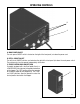
BUNN AF PR-2 ® AF PR-3 AFPR-3 VERSION DISCONTINUED The information in this manual is no longer current. OPERATING & SERVICE MANUAL BUNN-O-MATIC CORPORATION POST OFFICE BOX 3227 SPRINGFIELD, ILLINOIS 62708-3227 PHONE: (217) 529-6601 FAX: (217) 529-6644 28791.
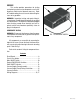
INTRODUCTION This equipment supplies a premixed liquid product to the hoppers on the CDS-2 or 3 dispensers. It is for indoor use only on a sturdy counter or shelf. WARRANTY Bunn-O-Matic Corp. (“Bunn”) warrants the equipment manufactured by it to be commercially free from defects in material and workmanship existing at the time of manufacture and appearing within one year from the date of installation. In addition: 1.
INITIAL SET-UP NOTE: This refill unit should not be used to initially fill the hopper. Running the motor for extended periods will trip the thermal switch. The thermal switch will reset, but requires up to 30 minutes of cooling time. NOTE: Hoses, clamps and product container connectors are not supplied. Fittings and labels are supplied. Make hose assemblies as required. 1. Assemble hoppers with probe housing assemblies to CDS-2, CDS-3 or modify existing hoppers using template provided. 2.
CLEANING RECOMMENDED WEEKLY CLEANING: This should be done in conjunction with the recommended weekly cleaning of your CDS-2 or CDS-3 machine. The CDS Hoppers must be empty before starting. 1. Prepare a 1 gallon cleaning solution consisting of 1 gallon of hot water and a sanitizing cleaner which contains 3-5% chlorine based sanitizer. Mix per manufacturers instructions 2. Remove connectors from each concentrate container and place them directly into the cleaning solution. 3.
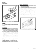
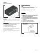
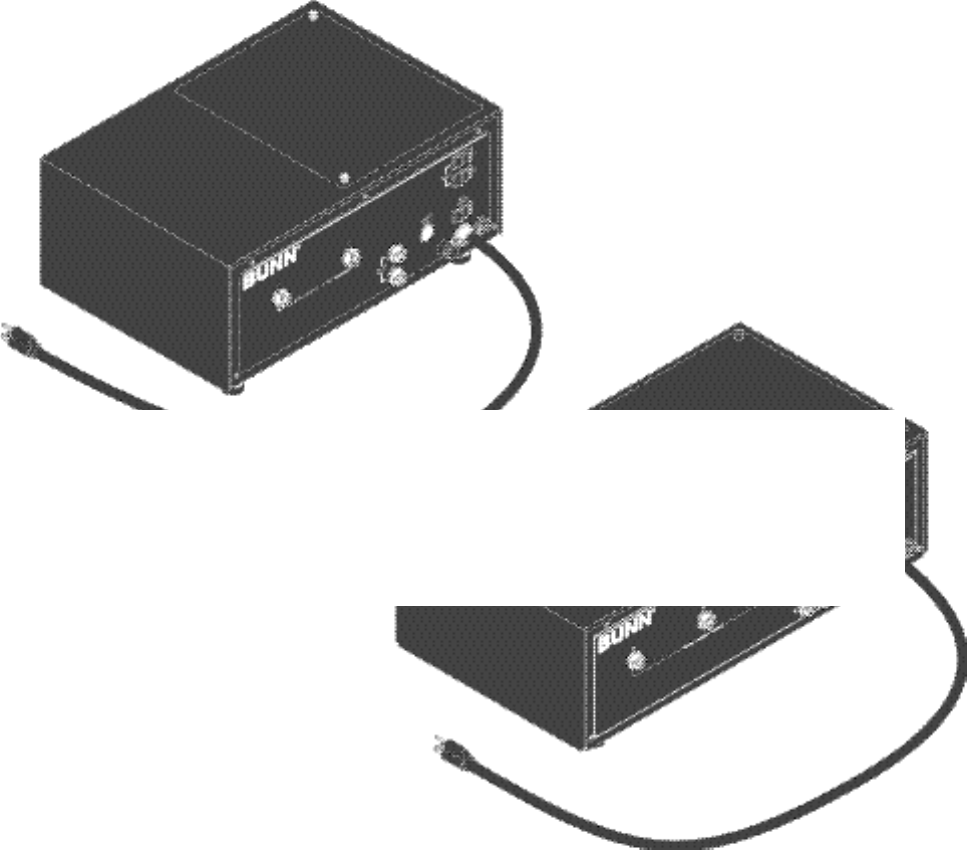
OPERATING CONTROLS B A P2052 A. MAIN POWER ON/OFF The main power ON/OFF switch is located on the right of the front panel just above the power cord. B. REFILL CIRCUIT ON/OFF The refill circuit ON/OFF switches are located on the right of the front panel just above the main power switch. These allow each circuit to operate independently of the other. C. PROBE CONTROL BOX LOW/OFF/HIGH On models equipped with a dual level probe, there is a LOW/OFF/HIGH switch located at the probe control box on the hopper.
TROUBLESHOOTING (cont.) PROBLEM PROBABLE CAUSE REMEDY Product will not dispense 1. Empty product container Replace or refill 2. No power or incorrect voltage to (A1) Check the outlet for 120 volts the dispenser on two wire 120 volt dispenser. (A2) Check the outlet for 200 volts or 240 volts ac for two wire 200 volt or 240 volt dispensers. (B) Check circuit breakers or fuses. Motor thermal cutout (motor stops running) 3. Signal cable unplugged Signal cable must be plugged in. 4.
SERVICE This section provides procedures for testing and replacing various major components used in this dispenser should service become necessary. Refer to Troubleshooting for assistance in determining the cause of any problem. WARNING - Inspection, testing, and repair of electrical equipment should be performed only by qualified service personnel. The dispenser should be unplugged when servicing, except when electrical tests are required and the test procedure specifically states to plug-in the dispenser.
SERVICE CIRCUIT BOARD FFO Removal and Replacement: 1. Disconnect the ten pin plug from the main wiring harness to the circuit board. 2. Remove the six #4-40 screws and spacers securing the circuit board to the solenoid mounting bracket. Remove circuit board and discard. 3. Install new circuit board using #4-40 screws and spacers to secure the circuit board to the vacuum switch mounting bracket. The spacers must be between the solenoid mounting bracket and the circuit board. 4. Refer to Fig.
SERVICE FUSE AND FUSE HOLDER Removal and Replacement: Fuse: 1. Remove the cap from the fuse holder. 2. Remove fuse from the fuse holder, inspect, if blown discard. 3. Install new 10 amp fuse in the fuse holder. 4. Reinstall fuse holder cap. FIG. 4 FUSE HOLDER Fuse Holder: 1. Disconnect the wires from the rear of the fuse holder. 2. Remove the nut securing the fuse holder to the front of the main mounting panel. 3. Push the fuse holder through the hole in the panel. 4.
SERVICE (cont.) MAIN ON/OFF SWITCH If voltage is present as described, proceed to #5. If voltage is not present as described, refer to the wiring diagrams and check the dispenser wiring harness. 5. Check for continuity across the switch terminals with the switch in the “ON” position. Continuity must not be present when the switch is in the “OFF” position. If continuity is present as described, reconnect the wires to the switch terminals. If continuity is not present as described, replace the switch. FIG.
SERVICE (cont.) PROBE SYSTEM Probe Boxes: 1. Disconnect the signal cable from the probe boxes. 2. Remove probe box from CDS hopper. 3. Place the switch on the probe box in the “HIGH” position. 4. Check the resistance across the box cable pins, see Fig. 8B. AFPR-2 & 3 FIG. 8B PROBE BOX CABLE PINS FIG. 8 PROBE SWITCHES P1539 5. With the probe box switch in the “LOW” position check the ohms across the pins, refer to Fig. 8B. 6.
SERVICE (cont.) wires to the switch terminals. If continuity is not present as described, replace the switch. Removal and Replacement: 1. Remove the wires from the switch terminals. 2. Compress the clips inside the autofill box and gently push the switch through the opening in the front of autofill box. 3. Push the new switch into the opening and spread the clips to hold switch in the autofill box. 4. Refer to Fig 13 when reconnecting the wires. REFILL SWITCHES #1 AFPR-2 & 3 FIG.
SERVICE (cont.) a) 120 volts ac for two wire 120 volt models. b) 200 to 240 volts ac for two wire 200 or 240 volt models. If voltage is present as described, replace the pump. If voltage is not present as described, refer to the wiring diagrams and check the main wiring harness. VACUUM/SUPPLY PUMP ASSEMBLY Pump Removal and Replacement: 1. Disconnect the wires from the pump leads. 2. Disconnect the input and output tubes. 3.
SERVICE (cont.) VACUUM/SUPPLY PUMP TUBE INSTALLATION 1. Separate the pump head from the pump body. Hold pump head as shown in Fig. 18, with roller in the 2, 6 10 o’clock positions. 2. Wrap tubing around rollers and hold as shown in Fig. 18. 3. Insert the slot of the tubing key (supplied), as shown in Fig. 18 on the rotor so the bottom edge of the key is pressing the tubing into the pump head cavity. 4.
SERVICE (cont.) Removal and Replacement: 1. Disconnect dispenser from the power source. 2. Remove the four thumb screws securing the right side pump head to the right side pump. 3. Disconnect the input tube from the pump to vacuum switch to be removed. 4. Remove the two #8-32 keps nuts securing the pump and bracket to main panel. 5. Disconnect the yellow and white wires from the pump. 6. Remove pump and bracket as an assembly. 7. Disconnect the input tubes from the vacuum switch to be replaced. 8.
28791.
28791.