
Instruction Manual


19
PMT INSTALLATION
Introduction Parts Description Operating Instructions Internet Updates Appendix
SECTION 2: INSTALLING THE PYROMETER AND THE PYROMETER CONNECTION HEAD PCH
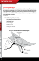
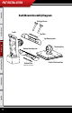
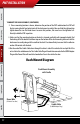
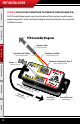
The PCH Assembly Diagram provides a quick visual description of all parts and pieces needed to acquire
pyrometer temperatures. The parts described in the diagram below will be referred to in this section of the
installation instructions.
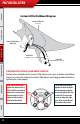
Pyrometer Lead (Red)
(Longest of the two leads)
Pyrometer Lead Terminals (Pyro 1)
(Red on right, Yellow on left)
Pyrometer Lead Terminals (Pyro 2)
(Red on right, Yellow on left)
PCH Cable
(To OBDll Adapter Plug)
Pyrometer Lead (Yellow)
(Shortest of the two leads)
Pyrometer Cable
(To Pyrometer Probe)
Velcro Strip
(Mounting Option)
Jumper
(Connects to Pyro 2)
Sheet Metal Screw
(Mounting Option)
PCH Assembly Diagram
PMT Installation