
Instruction Manual


13
PMT INSTALLATION
Introduction Parts Description Operating Instructions Internet Updates Appendix
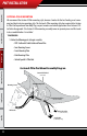
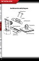
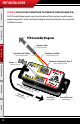
(To OBDII Adapter Plug)
(To Vehicle Fuse Box)
Cradle Cable
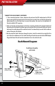
Custom A-Pillar Mount
with Cradle
Custom A-Pillar Pod Mount Diagram
Power Wire
Custom A-Pillar Pod
(Not Included)
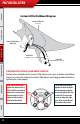
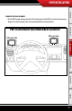
TIGHTENING THE CUSTOM APILLAR MOUNT SCREWS TIP
The four screws included with the Custom A-Pillar Mount work in pairs to perform two dierent
functions in securing the cradle to the Custom A-Pillar Mount. See the diagram below for details in
tightening the screws properly.
These two screw locations
tighten the mount to the A-
Pillar itself. Only completely
tighten these screws down
when the mount is in the
A-pillar and the A-pillar is
installed on the vehicle.
These two screw locations
tighten the front and back
mounting plates together
to create a tight t over the
cradle ball. Use these two
screws to adjust the tight-
ness of the swivel eect of
the cradle in the mount.
PMT Installation